Injection locking
Injection locking and injection pulling are the frequency effects that can occur when a harmonic oscillator is disturbed by a second oscillator operating at a nearby frequency. When the coupling is strong enough and the frequencies near enough, the second oscillator can capture the first oscillator, causing it to have essentially identical frequency as the second. This is injection locking. When the second oscillator merely disturbs the first but does not capture it, the effect is called injection pulling. Injection locking and pulling effects are observed in numerous types of physical systems, however the terms are most often associated with electronic oscillators or laser resonators.
Injection locking has been used in beneficial and clever ways in the design of early television sets and oscilloscopes, allowing the equipment to be synchronized to external signals at a relatively low cost. Injection locking has also been used in high performance frequency doubling circuits. However, injection locking and pulling, when unintended, can degrade the performance of phase locked loops and RF integrated circuits.
Injection from grandfather clocks to lasers
Injection pulling and injection locking can be observed in numerous physical systems where pairs of oscillators are coupled together. Perhaps the first to document these effects was Christiaan Huygens, the inventor of the pendulum clock, who was surprised to note that two pendulum clocks which normally would keep slightly different time nonetheless became perfectly synchronized when hung from a common beam. Modern researchers have confirmed his suspicion that the pendulums were coupled by tiny back-and-forth vibrations in the wooden beam.[1] The two clocks became injection locked to a common frequency.

In a modern-day voltage-controlled oscillator an injection-locking signal may override its low-frequency control voltage, resulting in loss of control. When intentionally employed, injection locking provides a means to significantly reduce power consumption and possibly reduce phase noise in comparison to other frequency synthesizer and PLL design techniques. In similar fashion, the frequency output of large lasers can be purified by injection locking them with high accuracy reference lasers (see injection seeder).
Injection-locked oscillator
An injection-locked oscillator (ILO) is usually based on cross-coupled LC oscillator. It has been employed for frequency division [2] or jitter reduction in PLL, with the input of pure sinusoidal waveform. It was employed in continuous mode clock and data recovery (CDR) or clock recovery to perform clock restoration from the aid of either preceding pulse generation circuit to convert non-return-to-zero (NRZ) data to pseudo-return-to-zero (PRZ) format[3] or nonideal retiming circuit residing at the transmitter side to couple the clock signal into the data.[4] Recently, the ILO was employed for burst mode clock recovery scheme.[5]
The operation of ILO is based on the fact that the local oscillation can be locked to the frequency and phase of external injection signal under proper conditions.
Unwanted injection locking
High-speed logic signals and their harmonics are potential threats to an oscillator. The leakage of these and other high frequency signals into an oscillator through a substrate concomitant with an unintended lock is unwanted injection locking.
Gain by injection locking
Injection locking can also provide a means of gain at a low power cost in certain applications.
Injection pulling
 |
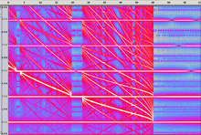
"Injection Locking and Pulling"
 Injection pulling and locking heard alternatively when one oscillator of two sweeps in frequency |
| Problems playing this file? See media help. | |
Injection (aka frequency) pulling occurs when an interfering frequency source disturbs an oscillator but is unable to injection lock it. The frequency of the oscillator is pulled towards the frequency source as can be seen in the spectrogram. The failure to lock may be due to insufficient coupling, or because the injection source frequency lies outside the locking window of the oscillator.
Entrainment
Entrainment has been used to refer to the process of mode locking of coupled driven oscillators, which is the process whereby two interacting oscillating systems, which have different periods when they function independently, assume a common period. The two oscillators may fall into synchrony, but other phase relationships are also possible. The system with the greater frequency slows down, and the other speeds up.
Dutch physicist Christiaan Huygens, the inventor of the pendulum clock, introduced the concept after he noticed, in 1666, that the pendulums of two clocks mounted on a common board had synchronized, and subsequent experiments duplicated this phenomenon. He described this effect as "odd sympathy". The two pendulum clocks synchronized with their pendulums swinging in opposite directions, 180° out of phase, but in-phase states can also result. Entrainment occurs because small amounts of energy are transferred between the two systems when they are out of phase in such a way as to produce negative feedback. As they assume a more stable phase relationship, the amount of energy gradually reduces to zero. In the realm of physics, Huygens' observations are related to resonance and the resonant coupling of harmonic oscillators, which also gives rise to sympathetic vibrations.
A 2002 study of Huygens' observations show that an antiphase stable oscillation was somewhat fortuitous, and that there are other possible stable solutions, including a "death state" where a clock stops running, depending on the strength of the coupling between the clocks.[6]
Mode locking between driven oscillators can be easily demonstrated using mechanical metronomes on a common, easily movable surface.[7][8] Such mode locking is important for many biological systems including the proper operation of pacemakers.[9]
The use of the word entrainment in the modern Physics literature most often refers to the movement of one fluid, or collection of particulates, by another (see Entrainment (hydrodynamics)). The use of the word to refer to mode locking of non-linear coupled oscillators appears mostly after about 1980, and remains relatively rare in comparison.
A similar coupling phenomenon was characterized in hearing aids when the adaptive feedback cancellation is used. This chaotic artifact (entrainment) is observed when correlated input signals are presented to an adaptive feedback canceller.
In recent years, aperiodic entrainment has been identified as an alternative form of entrainment that is of interest in biological rhythms.[10][11][12]
See also
- Injection-locked frequency divider
- Injection-locked PLL
- LC oscillator
- Electronic oscillator
- Burst mode clock and data recovery
- Entrainment (hydrodynamics)
- Brainwave synchronization
- Synchronization of chaos
- odd sympathy
References
- ↑ http://phys.org/news/2016-03-huygens-pendulum-synchronization.html - Researchers prove Huygens was right about pendulum synchronization
- ↑ M. Tiebout, "A CMOS direct injection-locked oscillator topology as high-frequency low-power frequency divider," IEEE Journal of Solid-State Circuits, vol. 39, pp. 1170-1174, 2004.
- ↑ M. De Matos, J. B. Begueret, H. Lapuyade, D. Belot, L. Escotte, and Y. Deval, "A 0.25um SiGe receiver front-end for 5GHz applications," SBMO/IEEE MTT-S International Conference on Microwave and Optoelectronics 2005, pp. 213-217.
- ↑ [54] T. Gabara, "An 0.25 μm CMOS injection locked 5.6 Gbit/s clock and data recovery cell," in Symposium on Integrated Circuits and Systems Design 1999, pp. 84 - 87.
- ↑ J. Lee and M. Liu, "A 20Gbit/s burst-mode CDR circuit using injection-locking technique," in IEEE International Solid-State Circuits Conference (ISSCC), pp. 46–586, 2007.
- ↑ M Bennett, M F Schatz, H Rockwood, andK Wiesenfeld, Proc. Roy. Soc. Lond. A 458 (2002) 563-579.
- ↑ J. Pantaleone, "Synchronization of Metronomes," American Journal of Physics, vol 70 (2002) 992–1000.
- ↑ Watch the synchronization of 32 metronomes CBS News, 2013 Sept 10
- ↑ G. B. Ermentrout and J. Rinzel, "Beyond a pacemaker's entrainment limit: phase walk-through," American Journal of Physiology – Regulatory, Integrative and Comparative Physiology, Vol 246 (1984) R102–R106.
- ↑ Mainen, Z. F., and Sejnowski, T. J. (1995) Reliability of spike timing in neocortical neurons. Science 268, 1503−1506.
- ↑ Mori, T., and Kai, S. (2002) Noise-Induced Entrainment and Stochastic Resonance in Human Brain Waves. Phys. Rev. Lett. 88, 218101.
- ↑ N.C. Butzin, P. Hochendoner, C.T. Ogle, P. Hill, and W.H. Mather. Marching along to an Offbeat Drum: Entrainment of Synthetic Gene Oscillators by a Noisy Stimulus. ACS Syn. Bio. (2015).
- Filter Entrainment Avoidance with a Frequency Domain Transform Algorithm
- Entrainment Avoidance with Pole Stabilization
- Entrainment Avoidance with a Transform Domain Algorithm
- Entrainment Avoidance with an Auto Regressive Filter
Further reading
* Wolaver, Dan H. 1991. Phase-Locked Loop Circuit Design, Prentice Hall, ISBN 0-13-662743-9, pages 95–105
- Adler, Robert (June 1946). "A Study of Locking Phenomena in Oscillators". Proceedings of the IRE. 34 (6): 351–357. doi:10.1109/JRPROC.1946.229930.
- Kurokawa, K. (October 1973). "Injection locking of microwave solid-state oscillators". Proceedings of the IEEE. 61 (10): 1386–1410. doi:10.1109/PROC.1973.9293.
* Lee, Thomas H. 2004. The Design of CMOS Radio-Frequency Integrated Circuits, Cambridge, ISBN 0-521-83539-9, pages 563–566