Electrodeless lamp

The internal electrodeless lamp or induction light is a gas discharge lamp in which the power required to generate light is transferred from outside the lamp envelope to the gas inside via an electric or magnetic field, in contrast with a typical gas discharge lamp that uses internal electrodes connected to the power supply by conductors that pass through the lamp envelope. There are two advantages to elimination of the internal electrodes:
- Extended lamp life, because the internal electrodes are usually the limiting factor in lamp life.
- The ability to use light-generating substances of higher efficiency that would react with internal metal electrodes in normal lamps.
Two systems are described below – plasma lamps, which use electrostatic induction to energize a bulb filled with sulfur vapor or metal halides, and fluorescent induction lamps, based upon a conventional fluorescent lamp bulb in which current is induced by an external coil of wire via electrodynamic induction.
History
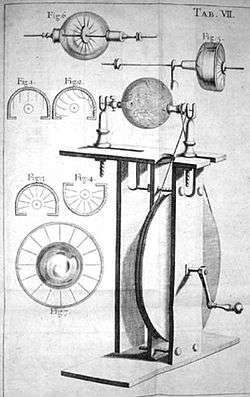
In 1705, the scientist Francis Hauksbee demonstrated that in a rotating glass globe with internal vacuum like in a barometer, filled with mercury, and statical charged by holding a hand against the rotating globe, a light phenomenon occurred, so bright that one could read a paper.
Nikola Tesla demonstrated wireless transfer of power to electrodeless lamps in his lectures and articles in the 1890s, and subsequently patented a system of light and power distribution on those principles.[1]
In 1967 and 1968, John Anderson of General Electric[2][3] applied for patents for electrodeless lamps. In 1971, Fusion UV Systems installed a 300-watt electrodeless microwave plasma UV lamp on a Coors can production line.[4] Philips introduced their QL induction lighting systems, operating at 2.65 MHz, in 1990 in Europe and in 1992 in the US. Matsushita had induction light systems available in 1992. Intersource Technologies also announced one in 1992, called the E-lamp. Operating at 13.6 MHz, it was to be available on the US market in 1993.
In 1990, Michael Ury, Charles Wood and colleagues formulated the concept of the sulphur lamp. With support from the United States Department of Energy, it was further developed in 1994 by Fusion Lighting of Rockville, Maryland, a spinoff of the Fusion UV division of Fusion Systems Corporation. Its origins are in microwave discharge light sources used for ultraviolet curing in the semiconductor and printing industries.
Since 1994, General Electric has produced its induction lamp Genura with an integrated ballast, operating at 2.65 MHz. In 1996, Osram started selling their Endura induction light system, operating at 250 kHz. It is available in the US as the Sylvania Icetron. In 1997, PQL Lighting introduced in the US the Superior Life Brand induction lighting systems. Most induction lighting systems are rated for 100,000 hours of use before requiring absolute component replacements.
In 2005, Amko Solara in Taiwan introduced induction lamps that can dim and use IP (Internet Protocol) based controls. Their lamps have a range from 12 to 400 watts and operate at 250 kHz.
From 1995, the former distributors of Fusion, Jenton / Jenact, expanded on the fact that energised UV-emitting plasmas act as lossy conductors to create a number of patents regarding electrodeless UV lamps for sterilising and germicidal uses.
Around 2000, a system was developed that concentrated radio frequency waves into a solid dielectric waveguide made of ceramic which energized a light-emitting plasma in a bulb positioned inside. This system, for the first time, permitted an extremely bright and compact electrodeless lamp. The invention has been a matter of dispute. Claimed by Frederick Espiau (then of Luxim, now of Topanga Technologies), Chandrashekhar Joshi and Yian Chang, these claims were disputed by Ceravision Limited.[5] A number of the core patents were assigned to Ceravision.[6][7]
In 2006, Luxim introduced a projector lamp product trade-named LIFI. The company further extended the technology with light source products in instrument, entertainment, street, area and architectural lighting applications among others throughout 2007 and 2008.
In 2009, Ceravision Limited introduced the first High Efficiency Plasma (HEP) lamp under the trade name Alvara. This lamp replaces the opaque ceramic waveguide used in earlier lamps with an optically clear quartz waveguide giving greatly increased efficiency. In previous lamps, though the burner, or bulb, was very efficient, the opaque ceramic waveguide severely obstructed the collection of light. A quartz waveguide allows all of the light from the plasma to be collected.
In 2012, Topanga Technologies introduced a line of advanced plasma lamps (APL), driven by a solid state radio frequency (RF) driver,[8] thereby circumventing the limited life of magnetron-based drivers, with system power of 127 and 230 watts and system efficacies of 96 and 87 lumen/watt, with a CRI of about 70.
Plasma lamps
Plasma lamps are a family of light sources that generate light by exciting a plasma inside a closed transparent burner or bulb using radio frequency (RF) power. Typically, such lamps use a noble gas or a mixture of these gases and additional materials such as metal halides, sodium, mercury or sulfur. A waveguide is used to constrain and focus the electrical field into the plasma. In operation the gas is ionized and free electrons, accelerated by the electrical field, collide with gas and metal atoms. Some electrons circling around the gas and metal atoms are excited by these collisions, bringing them to a higher energy state. When the electron falls back to its original state, it emits a photon, resulting in visible light or ultraviolet radiation depending on the fill materials.
The first plasma lamp was an ultraviolet curing lamp with a bulb filled with argon and mercury vapor developed by Fusion UV. That lamp led Fusion Systems to the development of the sulfur lamp, a bulb filled with argon and sulfur which is bombarded with microwaves through a hollow waveguide.
In the past, the reliability of the technology was limited by the magnetron used to generate the microwaves. Solid state RF generation can be used and gives long life. However, using solid state chips to generate RF is approximately fifty times more expensive currently than using a magnetron and so only appropriate for high value lighting niches. It has recently been shown by Dipolar of Sweden to be possible to greatly extend the life of magnetrons to over 40,000 hours[9] making low cost plasma lamps possible. Plasma lamps are currently produced by Ceravision and Luxim and in development by Topanga Technologies.
Ceravision has introduced a combined lamp and luminaire under the trade name Alvara for use in high bay and street lighting applications. It uses an optically clear quartz waveguide with an integral burner allowing all the light from the plasma to be collected. The small source also allows the luminaire to utilize more than 90% of the available light compared with 55% for typical HID fittings. Ceravision claims the highest Luminaire Efficacy Rating (LER)[10] of any light fitting on the market and to have created the first High Efficiency Plasma (HEP) lamp. Ceravision uses a magnetron to generate the required RF power and claim a life of 20,000 hours.
Luxim's Li-Fi lamp, claims 120 lumens per RF watt (i.e. before taking into account electrical losses).[11] The lamp has been used in Robe lighting's ROBIN 300 Plasma Spot moving headlight.[12] It was also used in a line of, now discontinued, Panasonic rear projection TVs.[13]
Magnetic induction lamps

Aside from the method of coupling energy into the mercury vapor, these lamps are very similar to conventional fluorescent lamps. Mercury vapor in the discharge vessel is electrically excited to produce short-wave ultraviolet light, which then excites internal phosphors to produce visible light. While still relatively unknown to the public, these lamps have been available since 1990. Unlike an incandescent lamp or conventional fluorescent lamps, there is no electrical connection going inside the glass bulb; the energy is transferred through the glass envelope solely by electromagnetic induction.
There are two main types of magnetic induction lamps: external core lamps and internal core lamps. The first commercially available and still widely used form of induction lamp is the internal core type. The external core type, which was commercialized later, has a wider range of applications and is available in round, rectangular and "olive" shaped form factors.
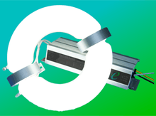
External core lamps are basically fluorescent lamps with magnetic cores wrapped around a part of the discharge tube. The core is usually made of ferrite, a ceramic material containing iron oxide and other metals. In external core lamps, high frequency energy from a special power supply called an electronic ballast is sent through wires that are wrapped in a coil around a toroidal ferrite core placed around the outside of a portion of the glass tube, creating a high frequency magnetic field within the ferrite core. Since the magnetic permeability of the ferrite is hundreds or thousands of times higher than that of the surrounding air or glass, and the ferrite core provides a closed path for the magnetic field, virtually all of the magnetic field is contained inside the ferrite core. As shown in Faraday's law of induction, the time varying magnetic field in the core will generate a time varying electric voltage in any closed path that encloses the time varying magnetic field. The discharge tube forms one such closed path around the ferrite core, and in that manner the time varying magnetic field in the core generates a time varying electric field in the discharge tube, There is no need for the magnetic field to penetrate the discharge tube. The electric field generated by the time varying magnetic field drives the mercury-rare gas discharge in the same way the discharge is driven by the electric field in a conventional fluorescent lamp. The primary winding on the ferrite core, the core, and the discharge form a transformer, with the discharge being a one-turn secondary on that transformer.
The discharge tube contains a low pressure of a rare gas such as argon and mercury vapor. The mercury atoms are provided by a drop of liquid mercury or by a semi-solid amalgam of mercury and other metals such as bismuth, lead or tin. Some of the liquid mercury or the mercury in the amalgam vaporizes to provide the mercury vapor. The electric field ionizes some of the mercury atoms to produce free electrons, and then accelerates those free electrons. When the free electrons collide with mercury atoms, some of those atoms absorb energy from the electrons and are “excited” to higher energy levels. After a short delay, the excited mercury atoms spontaneously relax to their original lower energy state and emit a UV photon with the excess energy. As in a conventional fluorescent tube, the UV photon diffuses through the gas to the inside of the outer bulb, and is absorbed by the phosphor coating that surface, transferring its energy to the phosphor. When the phosphor then relaxes to its original, lower energy state, it emits visible light. In this way the UV photon is down-converted to visible light by the phosphor coating on the inside of the tube. The glass walls of the lamp prevent the emission of the UV photons because ordinary glass blocks UV radiation at the 253.7 nm and shorter wavelengths.
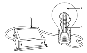
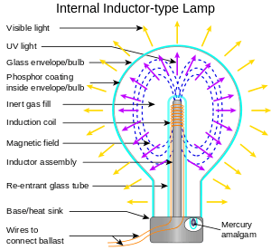
In the internal core form (see diagram), a glass tube (B) protrudes bulb-wards from the bottom of the discharge vessel (A), forming a re-entrant cavity. This tube contains an antenna called a power coupler, which consists of a coil wound over a cylindrical ferrite core. The coil and ferrite forms the inductor which couples the energy into the lamp interior
The antenna coils receive electric power from the electronic ballast (C) that generates a high frequency. The exact frequency varies with lamp design, but popular examples include 13.6 MHz, 2.65 MHz and 250 kHz. A special resonant circuit in the ballast produces an initial high voltage on the coil to start a gas discharge; thereafter the voltage is reduced to normal running level.
The system can be seen as a type of transformer, with the power coupler (inductor) forming the primary coil and the gas discharge arc in the bulb forming the one-turn secondary coil and the load of the transformer. The ballast is connected to mains electricity, and is generally designed to operate on voltages between 100 and 277 VAC at a frequency of 50 or 60 Hz, or on a voltage between 100 and 400 VDC for battery fed emergency light systems. Many ballasts are available in low voltage models so can also be connected to DC voltage sources like batteries for emergency lighting purposes or for use with renewable energy (solar & wind) powered systems.
In other conventional gas discharge lamps, the electrodes are the part with the shortest life, limiting the lamp lifespan severely. Since an induction lamp has no electrodes, it can have a very long service life. For induction lamp systems with a separate ballast, the service life can be as long as 100,000 hours, which is 11.4 years continuous operation. For induction lamps with integrated ballast, the lifespan is in the 15,000 to 50,000 hours range. Extremely high-quality electronic circuits are needed for the ballast to attain such a long service life. Such lamps are typically used in commercial or industrial applications. Typically operations and maintenance costs are significantly lower with induction lighting systems due to their industry average 100,000 hour life cycle and five to ten year warranty.
Advantages

- Long lifespan due to the lack of electrodes – Strictly speaking almost indefinite on the lamp itself but between 25,000 and 100,000 hours depending on lamp model and quality of electronics used, comparable to low quality LEDs of the 1970s;
- Very high energy conversion efficiency of between 62 and 90 Lumens/Watt [higher power lamps are more energy efficient];
- High power factor due to the low loss of the high frequency electronic ballasts which are typically between 95% and 98% efficient;
- Minimal Lumen depreciation (declining light output with age) compared to other lamp types as filament evaporation and depletion is absent;
- "Instant-on" and hot re-strike, unlike most HID lamps used in commercial-industrial lighting applications (such as mercury-vapor lamp, sodium-vapor lamp and metal halide lamp);
- Environmentally friendly as induction lamps use less energy, and use less mercury per hour of operation than conventional lighting due to their long lifespan. The mercury is in a solid form and can be easily recovered if the lamp is broken, or for recycling at end-of-life.
These benefits offer considerable cost savings of between 35% and 55% in energy and maintenance costs for induction lamps compared to other types of commercial and industrial lamps which they replace.
Disadvantages
- Some models of internal inductor lamps that use high frequency ballasts can produce radio frequency interference (RFI) which interferes with radio communications in the area. Newer, external inductor type lamps use low frequency ballasts that usually have FCC or other certification, thus suggesting compliance with RFI regulations.
- Some types of inductor lamps contain mercury, which is highly toxic if released to the environment.
See also
References
- ↑ "Experiments with Alternate Currents of Very High Frequency and Their Application to Methods of Artificial Illumination", AIEE, Columbia College, N.Y., May 20, 1891
- ↑ Electrodeless gaseous electric discharge devices utilizing ferrite cores
- ↑ High frequency electrodeless fluorescent lamp assembly
- ↑ A History of Heraeus Noblelight Fusion UV and its Industry Leadership in UV Curing Equipment and Products
- ↑ Ceravision Steps up Legal Action Against Luxim to Recover IP
- ↑ Microwave Energized Plasma Lamp with Solid Dielectric Waveguide
- ↑ Plasma Lamp with Dielectric Waveguide
- ↑ Topanga :: Home
- ↑ Ceravision & Dipolar Form Global Alliance to Take Ultra-Efficient Lighting Technology to... - MILTON KEYNES, England, May 19 /PRNewswire/
- ↑ Procedure for Determining Luminaire Efficacy Ratings for High-Intensity Discharge (HID) Industrial Luminaires Archived May 1, 2009, at the Wayback Machine.
- ↑ "A lightbulb powered by radio waves". cnet. 2007-08-23.
- ↑ "Robe Launches ROBIN 300 Plasma Spot". Robe lighting. 2009-04-27.
- ↑ "The gift of LIFI: Panasonic projection TVs don't burn out". cnet. 2007-01-09.