Electric power distribution
Electric power distribution is the final stage(step) in the delivery of electric power; it carries electricity from the transmission system to individual consumers. Distribution substations connect to the transmission system and lower the transmission voltage to medium voltage ranging between 2 kV and 35 kV with the use of transformers. Primary distribution lines carry this medium voltage power to distribution transformers located near the customer's premises. Distribution transformers again lower the voltage to the utilization voltage of household appliances and typically feed several customers through secondary distribution lines at this voltage. Commercial and residential customers are connected to the secondary distribution lines through service drops. Customers demanding a much larger amount of power may be connected directly to the primary distribution level or the subtransmission level.
History
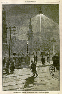
Electric power distribution only became necessary in the 1880s when electricity started being generated at power stations. Before that electricity was usually generated where it was used. The first power distribution systems installed in European and US cites were used to supply lighting: arc lighting running on very high voltage (usually higher than 3000 volt) alternating current (AC) or direct current (DC), and incandescent lighting running on low voltage (100 volt) direct current.[1] Both were supplanting gas lighting systems, with arc lighting taking over large area/street lighting, and incandescent lighting replacing gas for business and residential lighting.
Due to the high voltages used in arc lighting, a single generating station could supply a long string of lights, up to 7-mile (11 km) long circuits,[2] since the capacity of a wire is proportional to the square of the current traveling on it, each doubling of the voltage would allow the same size cable to transmit the same amount of power four times the distance. Direct current indoor incandescent lighting systems (for example the first Edison Pearl Street Station installed in 1882), had difficulty supplying customers more than a mile away due to the low 110 volt system being used throughout the system, from the generators to the final use. The Edison DC system needed thick copper conductor cables, and the generating plants needed to be within about 1.5 miles (2.4 km) of the farthest customer to avoid excessively large and expensive conductors.
Introduction of the AC transformer
Trying to deliver electricity long distance at high voltage and then reducing it to a fractional voltage for indoor lighting became a recognized engineering roadblock to electric power distribution with many, not very satisfactory, solutions tested by lighting companies. The mid-1880s saw a breakthrough with the development of functional AC transformers that allowed the voltage to be "stepped up" to much higher transmission voltages and then dropped down to a lower end user voltage. With much cheaper transmission costs and the greater economies of scale of having large generating plants supply whole cities and regions, the use of AC spread rapidly.
In the US the competition between direct current and alternating current took a personal turn in the late 1880s in the form of a "War of Currents" when Thomas Edison started attacking George Westinghouse and his development of the first US AC transformer systems, pointing out all the deaths caused by high voltage AC systems over the years and claiming any AC system was inherently dangerous.[3] Edison's propaganda campaign was short lived with his company switching over to AC in 1892.
AC became the dominant form of transmission of power with innovations in Europe and the US in electric motor designs and the development of engineered universal systems allowing the large number of legacy systems to be connected to large AC grids.[4][5]
In the first half of the 20th century, the electric power industry was vertically integrated, meaning that one company did generation, transmission, distribution, metering and billing. Starting in the 1970s and 1980s nations began the process of deregulation and privatisation, leading to electricity markets. The distribution system would remain regulated, but generation, retail, and sometimes transmission systems were transformed into competitive markets.
Generation and transmission
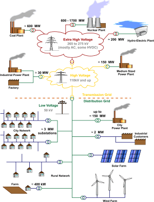
Electric power begins at a generating station, where the potential difference can be as high as 13,800 volts.[6] AC is usually used. Users of large amounts of DC power such as some railway electrification systems, telephone exchanges and industrial processes such as aluminium smelting usually either operate their own or have adjacent dedicated generating equipment, or use rectifiers to derive DC from the public AC supply. However, High-voltage DC can be advantageous for isolating alternating-current systems or controlling the quantity of electricity transmitted. For example, Hydro-Québec has a direct-current line which goes from the James Bay region to Boston.[7]
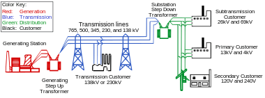
From the generating station it goes to the generating station’s switchyard where a step-up transformer increases the voltage to a level suitable for transmission, from 44kV to 765kV. Once in the transmission system, electricity from each generating station is combined with electricity produced elsewhere. Electricity is consumed as soon as it is produced. It is transmitted at a very high speed, close to the speed of light.
Distribution overview
The transition from transmission to distribution happens in a power substation, which has the following functions:[8]
- Circuit breakers and switches enable the substation to be disconnected from the transmission grid or for distribution lines to be disconnected.
- Transformers step down transmission voltages, 35kV or more, down to primary distribution voltages. These are medium voltage circuits, usually 600-35,000 V.[9]
- From the transformer, power goes to the busbar that can split the distribution power off in multiple directions. The bus distributes power to distribution lines, which fan out to customers.
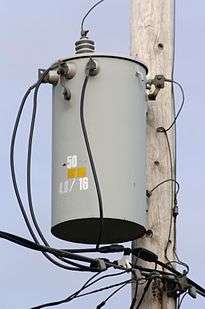
Urban distribution is mainly underground, sometimes in common utility ducts. Rural distribution is mostly above ground with utility poles, and suburban distribution is a mix.[9] Closer to the customer, a distribution transformer steps the primary distribution power down to a low-voltage secondary circuit, usually 120 or 240V, depending on the region. The power comes to the customer via a service drop and an electricity meter. The final circuit in an urban system may be less than 50 feet, but may be over 300 feet for a rural customer.[9]
Primary distribution
Primary distribution voltages are 22kV or 11 kV.[10] Only large consumers are fed directly from distribution voltages; most utility customers are connected to a transformer, which reduces the distribution voltage to the low voltage used by lighting and interior wiring systems.
Voltage varies according to its role in the supply and distribution system. According to international standards, there are initially two voltage groups: low voltage (LV): up to and including 1kV AC (or 1.5kV DC) and high voltage (HV): above 1 kV AC (or 1.5 kV DC).[11]
Network configurations

Distribution networks are divided into two types, radial or network.[12] A radial system is arranged like a tree where each customer has one source of supply. A network system has multiple sources of supply operating in parallel. Spot networks are used for concentrated loads. Radial systems are commonly used in rural or suburban areas.
Radial systems usually include emergency connections where the system can be reconfigured in case of problems, such as a fault or required replacement. This can be done by opening and closing switches. It may be acceptable to close a loop for a short time.
Long feeders experience voltage drop (power factor distortion) requiring capacitors to be installed.
Reconfiguration, by exchanging the functional links between the elements of the system, represents one of the most important measures which can improve the operational performance of a distribution system. The problem of optimization through the reconfiguration of a power distribution system, in terms of its definition, is a historical single objective problem with constraints. Since 1975, when Merlin and Back[13] introduced the idea of distribution system reconfiguration for active power loss reduction, until nowadays, a lot of researchers have proposed diverse methods and algorithms to solve the reconfiguration problem as a single objective problem. Some authors have proposed Pareto optimality based approaches (including active power losses and reliability indices as objectives). For this purpose, different artificial intelligence based methods have been used: microgenetic,[14] branch exchange,[15] particle swarm optimization[16] and non-dominated sorting genetic algorithm.[17]
Rural services
Rural electrification systems tend to use higher distribution voltages because of the longer distances covered by distribution lines (see Rural Electrification Administration). 7.2, 12.47, 25, and 34.5 kV distribution is common in the United States; 11 kV and 33 kV are common in the UK, Australia and New Zealand; 11 kV and 22 kV are common in South Africa. Other voltages are occasionally used. Distribution in rural areas may be only single-phase if it is not economical to install three-phase power for relatively few and small customers.
Rural services normally try to minimize the number of poles and wires. Single-wire earth return (SWER) is the least expensive, with one wire. It uses higher voltages (than urban distribution), which in turn permits use of galvanized steel wire. The strong steel wire allows for less expensive wide pole spacing. In rural areas a pole-mount transformer may serve only one customer.
Higher voltage split-phase or three phase service, at a higher infrastructure and a higher cost, provide increased equipment efficiency and lower energy cost for large agricultural facilities, petroleum pumping facilities, or water plants.
In New Zealand, Australia, Saskatchewan, Canada, and South Africa, single wire earth return systems (SWER) are used to electrify remote rural areas.
Secondary distribution
Electricity is delivered at a frequency of either 50 or 60 Hz, depending on the region. It is delivered to domestic customers as single-phase electric power In some countries as in Europe a three phase supply may be made available for larger properties. Seen in an oscilloscope, the domestic power supply in North America would look like a sine wave, oscillating between -170 volts and 170 volts, giving an effective voltage of 120 volts.[18] Three-phase power is more efficient in terms of power delivered per cable used, and is more suited to running large electric motors. Some large European appliances may be powered by three-phase power, such as electric stoves and clothes dryers.
A ground connection is normally provided for the customer's system as well as for the equipment owned by the utility. The purpose of connecting the customer's system to ground is to limit the voltage that may develop if high voltage conductors fall down onto lower-voltage conductors which are usually mounted lower to the ground, or if a failure occurs within a distribution transformer. Earthing systems can be TT, TN-S, TN-C-S or TN-C.
Regional variations

220-240 volt systems
Most of the world uses 50 Hz 220 or 230 V single phase 400V 3 phase for residential and light industrial services. In this system, the primary distribution network supplies a few substations per area, and the 230 V power from each substation is directly distributed. A live (hot) wire and neutral are connected to the building for each phase of three phase service. Single-phase distribution is used where motor loads are light. In Europe, electricity is normally distributed for industry and domestic use by the three-phase, four wire system. This gives a three-phase voltage of 400 volts wye service and a single-phase voltage of 230 volts. In the UK a typical urban or suburban low-voltage substation would normally be rated between 150 kVA and 1 MVA and supply a whole neighborhood of a few hundred houses. For industrial customers, 3-phase 690 / 400 volt is also available, or may be generated locally.. Large industrial customers have their own transformer(s) with an input from 11 kV to 220 kV.
110-120 volt systems
Most of the Americas use 60 Hz AC, the 120/240 volt split phase system domestically and three phase for larger installations. Compared to European systems, North American ones have more step-down transformers near customers. This is because the higher domestic voltage used in Europe (230 V vs 120 V) may be carried over a greater distance with acceptable power loss. North American transforms usually power homes at 240 volts, similar to Europe's 230 volts. It is the split-phase that allows use of 120 volts in the home. The transformers actually provide 240 volts, not 120, so power can be carried over a greater distance.
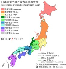
In the electricity sector in Japan, the standard frequencies for AC are 50 and 60 Hz. In Japan parts of the country use 50 Hz, while other parts use 60 Hz.[19] This is a relic of the 1800s. Some local providers in Tokyo imported 50 Hz German equipment, while the local power providers in Osaka brought in 60 Hz generators from the United States. The grids grew until eventually the entire country was wired. Today the frequency is 50 Hz in Eastern Japan (including Tokyo, Yokohama, Tohoku, and Hokkaido) and 60 Hertz in Western Japan (including Nagoya, Osaka, Kyoto, Hiroshima, Shikoku, and Kyushu).[20]
Most household appliances are made to work on either frequency. The problem of incompatibility came into the public eye when the 2011 Tōhoku earthquake and tsunami knocked out about a third of the east’s capacity, and power in the west couldn’t be fully shared with the east, since the country does not have a common frequency.[19]
There are four high-voltage direct current (HVDC) converter stations that move power across Japan’s AC frequency border. Shin Shinano is a back-to-back HVDC facility in Japan which forms one of four frequency changer stations that link Japan's western and eastern power grids. The other three are at Higashi-Shimizu, Minami-Fukumitsu and Sakuma Dam. Together they can move up to 1.2 GW of power east or west.[21]
240 volt systems and 120 volt outlets
Most modern North American homes are wired to receive 240 volts from the transformer, and through the use of split-phase electrical power, can have both 120 volt receptacles and 240 volt receptacles. The 120 volts is typically used for lighting and most wall outlets. The 240 volt outlets are usually placed where the water heater and clothes dryer would go. Sometimes a 240 volt outlet is mounted in the garage for machinery or for charging an electric car.
See also
- C37.94 – IEEE standard to interconnect tele-protection and multiplexer devices of power utility companies
- Cost of electricity by source
- Dynamic voltage restoration
- Electricity distribution companies by country
- Electric utility
- Electricity generation
- Electricity retailing
- Network protector
- Power distribution unit
- Transmission system operator
References
- ↑ Quentin R. Skrabec, The 100 Most Significant Events in American Business: An Encyclopedia, ABC-CLIO - 2012, page 86
- ↑ Berly, J. (1880-03-24). "Notes on the Jablochkoff System of Electric Lighting". Journal of the Society of Telegraph Engineers. Institution of Electrical Engineers. IX (32): 143. Retrieved 2009-01-07.
- ↑ Garrison, Webb B. (1983). Behind the headlines: American history's schemes, scandals, and escapades. Stackpole Books. p. 107.
- ↑ Parke Hughes, Thomas (1993). Networks of Power: Electrification in Western Society, 1880-1930. JHU Press. pp. 120–121.
- ↑ Garud, Raghu; Kumaraswamy, Arun; Langlois, Richard (2009). Managing in the Modular Age: Architectures, Networks, and Organizations. John Wiley & Sons. p. 249.
- ↑ "Power Transmission and Distribution | Hydro-Québec". www.hydroquebec.com. Retrieved 2016-03-08.
- ↑ "Extra-High-Voltage Transmission | 735 kV | Hydro-Québec". www.hydroquebec.com. Retrieved 2016-03-08.
- ↑ "How Power Grids Work". HowStuffWorks. Retrieved 2016-03-18.
- 1 2 3 Short, T.A. (2014). Electric Power Distribution Handbook. Boca Raton, Florida, USA: CRC Press. pp. 1–33. ISBN 978-1-4665-9865-2.
- ↑ Chan, F. "Electric Power Distribution Systems". Electrical Engineering (PDF). Retrieved 12 March 2016.
- ↑ Planning of Electric Power Distribution. https://w3.siemens.com/powerdistribution/global/EN/consultant-support/download-center/tabcardpages/Documents/Planning-Manuals/Planning_of_Electric_Power_Distribution_Technical_Principles.pdf: Siemens. 2015.
- ↑ Abdelhay A. Sallam and Om P. Malik (May 2011). Electric Distribution Systems. IEEE Computer Society Press. p. 21. ISBN 9780470276822.
- ↑ Merlin, A.; Back, H. Search for a Minimal-Loss Operating Spanning Tree Configuration in an Urban Power Distribution System. In Proceedings of the 1975 Fifth Power Systems Computer Conference (PSCC), Cambridge, UK, 1–5 September 1975; pp. 1–18.
- ↑ Mendoza, J.E.; Lopez, M.E.; Coello, C.A.; Lopez, E.A. Microgenetic multiobjective reconfiguration algorithm considering power losses and reliability indices for medium voltage distribution network. IET Gener. Transm. Distrib. 2009, 3, 825–840.
- ↑ Bernardon, D.P.; Garcia, V.J.; Ferreira, A.S.Q.; Canha, L.N. Multicriteria distribution network reconfiguration considering subtransmission analysis. IEEE Trans. Power Deliv. 2010, 25, 2684–2691.
- ↑ Amanulla, B.; Chakrabarti, S.; Singh, S.N. Reconfiguration of power distribution systems considering reliability and power loss. IEEE Trans. Power Deliv. 2012, 27, 918–926.
- ↑ Tomoiagă, B.; Chindriş, M.; Sumper, A.; Sudria-Andreu, A.; Villafafila-Robles, R. Pareto Optimal Reconfiguration of Power Distribution Systems Using a Genetic Algorithm Based on NSGA-II. Energies 2013, 6, 1439-1455.
- ↑ "How Power Grids Work". HowStuffWorks. Retrieved 2016-03-18.
- 1 2 Gordenker, Alice (2011-07-19). "Japan's incompatible power grids". The Japan Times Online. ISSN 0447-5763. Retrieved 2016-03-12.
- ↑ "Electricity in Japan". Japan-Guide.com. Retrieved 2016-03-12.
- ↑ "Why Japan's Fragmented Grid Can't Cope". Spectrum.IEEE.org. Retrieved 2016-03-12.
External links
| Wikimedia Commons has media related to Electrical distribution. |
| Wikiversity has learning materials about Distribution of Electrical Power |
- IEEE Power Engineering Society
- IEEE Power Engineering Society Distribution Subcommittee
- U.S. Department of Energy Electric Distribution website