Eddy current brake
An eddy current brake, like a conventional friction brake, is a device used to slow or stop a moving object by dissipating its kinetic energy as heat. However, unlike electro-mechanical brakes, in which the drag force used to stop the moving object is provided by friction between two surfaces pressed together, the drag force in an eddy current brake is an electromagnetic force between a magnet and a nearby conductive object in relative motion, due to eddy currents induced in the conductor through electromagnetic induction.
A conductive surface moving past a stationary magnet will have circular electric currents called eddy currents induced in it by the magnetic field, as described by Faraday's law of induction. By Lenz's law, the circulating currents will create their own magnetic field which opposes the field of the magnet. Thus the moving conductor will experience a drag force from the magnet that opposes its motion, proportional to its velocity. The electrical energy of the eddy currents is dissipated as heat due to the electrical resistance of the conductor.
In an eddy current brake the magnetic field may be created by a permanent magnet, or an electromagnet so the braking force can be turned on and off or varied by varying the electric current in the electromagnet's windings. Another advantage is that since the brake does not work by friction, there are no brake shoe surfaces to wear out, necessitating replacement, as with friction brakes. A disadvantage is that since the braking force is proportional to velocity the brake has no holding force when the moving object is stationary, as is provided by static friction in a friction brake, so in vehicles it must be supplemented by a friction brake.
Eddy current brakes are used to slow high-speed trains and roller coasters, to stop powered tools quickly when power is turned off, and in electric meters used by electric utilities.
How it works


An eddy current brake consists of a conductive piece of metal, either a straight bar or a disk, which moves through the magnetic field of a magnet, either a permanent magnet or an electromagnet. When it moves past the stationary magnet, the magnet exerts a drag force on the metal which opposes its motion, due to circular electric currents called eddy currents induced in the metal by the magnetic field.
See the diagram at right. It shows a metal sheet (C) moving to the right under a magnet. The magnetic field (B, green arrows) of the magnet's north pole N passes down through the sheet. Since the metal is moving, the magnetic flux through sheet is changing. At the part of the sheet under the leading edge of the magnet (left side) the magnetic field through the sheet is increasing as it gets nearer the magnet. From Faraday's law of induction, this field induces a counterclockwise flow of electric current (I, red), in the sheet. This is the eddy current. In contrast, at the trailing edge of the magnet (right side) the magnetic field through the sheet is decreasing, inducing a clockwise eddy current in the sheet.
Another way to understand the action is to see that the free charge carriers (electrons) in the metal sheet are moving to the right, so the magnetic field exerts a sideways force on them due to the Lorentz force. Since the velocity v of the charges is to the right and the magnetic field B is directed down, from the right hand rule the Lorentz force on positive charges qv×B is toward the rear. This causes a current I toward the rear under the magnet, which circles around through parts of the sheet outside the magnetic field in two currents, clockwise to the right and counterclockwise to the left, to the front of the magnet again. The mobile charge carriers in the metal, the electrons, actually have a negative charge, so their motion is opposite in direction to the conventional current shown.
Each of these circular currents creates a counter magnetic field (blue arrows), which due to Lenz's law opposes the change in magnetic field, causing a drag force on the sheet which is the braking force exerted by the brake. At the leading edge of the magnet (left side) by the right hand rule the counterclockwise current creates a magnetic field pointed up, opposing the magnet's field, causing a repulsive force between the sheet and the leading edge of the magnet. In contrast, at the trailing edge (right side), the clockwise current causes a magnetic field pointed down, in the same direction as the magnet's field, creating an attractive force between the sheet and the trailing edge of the magnet. Both of these forces oppose the motion of the sheet. The kinetic energy which is consumed overcoming this drag force is dissipated as heat by the currents flowing through the resistance of the metal, so the metal gets warm under the magnet.
The braking force of an eddy current brake is exactly proportional to the velocity V, so it acts similar to viscous friction in a liquid. When the conductive sheet is stationary, the magnetic field through each part of it is constant, not changing with time, so no eddy currents are induced, and there is no force between the magnet and the conductor. Thus an eddy current brake has no holding force.
Eddy current brakes come in two geometries:
- In a linear eddy current brake, the conductive piece is a straight rail or track that the magnet moves along.
- In a circular, disk or rotary eddy current brake, the conductor is a flat disk rotor that turns between the poles of the magnet.
The physical working principle is the same for both.
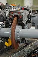
Disk eddy current brakes

(right) Permanent magnet eddy current brake used in a 1970s electricity meter
Disk electromagnetic brakes are used on vehicles such as trains, and power tools such as circular saws, to stop the blade quickly when the power is turned off. A disk eddy current brake consists of a conductive non-ferromagnetic metal disc (rotor) attached to the axle of the vehicle's wheel, with an electromagnet located with its poles on each side of the disk, so the magnetic field passes through the disk. The electromagnet allows the braking force to be varied. When no current is passed through the electromagnet's winding, there is no braking force. When the driver steps on the brake pedal, current is passed through the electromagnet windings, creating a magnetic field, The larger the current in the winding, the larger the eddy currents and the stronger the braking force. Power tool brakes use permanent magnets, which are moved adjacent to the disk by a linkage when the power is turned off. The kinetic energy of the vehicle's motion is dissipated in Joule heating by the eddy currents passing through the disk's resistance, so like conventional friction disk brakes, the disk becomes hot. Unlike in the linear brake below, the metal of the disk passes repeatedly through the magnetic field, so disk eddy current brakes get hotter than linear eddy current brakes.
Japanese Shinkansen trains had employed circular eddy current brake system on trailer cars since 100 Series Shinkansen. However, N700 Series Shinkansen abandoned eddy current brakes in favour of regenerative brakes, since 14 of the 16 cars in the trainset used electric motors. In regenerative brakes, the motor that drives the wheel is used as a generator to produce electric current, which can be used to charge a battery, so the energy can be used again.
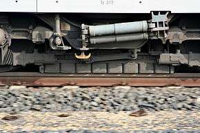
Linear eddy current brakes

Linear eddy current brakes are used on some vehicles that ride on rails, such as trains. They are used on roller coasters, to stop the cars smoothly at the end of the ride.
The linear eddy current brake consists of a magnetic yoke with electrical coils positioned along the rail, which are being magnetized alternating as south and north magnetic poles. This magnet does not touch the rail, but is held at a constant small distance from the rail of approximately 7 mm (the eddy current brake should not be confused with another device, the magnetic brake, in wide use in railways, which exerts its braking force by friction of a brake shoe with the rail). It works the same as a disk eddy current brake, by inducing closed loops of eddy current in the conductive rail, which generate counter magnetic fields which oppose the motion of the train.
The kinetic energy of the moving vehicle is converted to heat by the eddy current flowing through the electrical resistance of the rail, which leads to a warming of the rail. An advantage of the linear brake is that since each section of rail passes only once through the magnetic field of the brake, in contrast to the disk brake in which each section of the disk passes repeatedly through the brake, the rail doesn't get as hot as a disk, so the linear brake can dissipate more energy and have a higher power rating than disk brakes.
The eddy current brake does not have any mechanical contact with the rail, and thus no wear, and creates no noise or odor. The eddy current brake is unusable at low speeds, but can be used at high speeds both for emergency braking and for regular braking.[1]
The TSI (Technical Specifications for Interoperability) of the EU for trans-European high-speed rail recommends that all newly built high-speed lines should make the eddy current brake possible.
The first train in commercial circulation to use such a braking system has been the ICE 3.
Modern roller coasters also use this type of braking, but in order to avoid the risk posed by potential power outages, they utilize permanent magnets instead of electromagnets, thus not requiring any power supply, however, without the possibility to adjust the braking strength as easily as with electromagnets.
Lab experiment
In physics education a simple experiment is sometimes used to illustrate eddy currents and the principle behind magnetic braking. When a strong magnet is dropped down a vertical conducting pipe, eddy currents are induced in the pipe, and these retard the descent of the magnet, so it falls slower than it would if free-falling. As one set of authors explained
If one views the magnet as an assembly of circulating atomic currents moving through the pipe, [then] Lenz’s law implies that the induced eddies in the pipe wall counter circulate ahead of the moving magnet and co-circulate behind it. But this implies that the moving magnet is repelled in front and attracted in rear, hence acted upon by a retarding force.[2]
In typical experiments, students measure the slower time of fall of the magnet through a copper tube compared with a cardboard tube, and may use an oscilloscope to observe the pulse of eddy current induced in a loop of wire wound around the pipe when the magnet falls through.[3] to use of multiple magnets.[4]
See also
| Wikimedia Commons has media related to Eddy current brakes. |
- Telma retarder – an eddy current brake system made by Telma, a company that is part of the Valeo group
- Regenerative braking – generates electricity rather than heat and hence is usually more energy efficient
- Electromagnetic brakes (or electro-mechanical brakes) – use the magnetic force to press the brake mechanically on the rail
- Linear induction motor can be used as a regenerative brake
Notes
- ↑ "Wirbelstrombremse im ICE 3 als Betriebsbremssystem hoher Leistung" ("Eddy-current brake in the ICE 3 as high-efficiency service brake system", by Jürgen Prem, Stefan Haas, Klaus Heckmann, in "electrische bahnen" Vol 102 (2004), No. 7, pages 283ff
- ↑ M.H. Partori & E.J. Morris (2006) "Electrodynamics of a magnet moving through a conducting pipe" Canadian Journal of Physics 84:253–71
- ↑ C. S. Maclatchy, P, Backman, L. Bogan (1993) "A quantitative magnetic braking experiment", American Journal of Physics 61:1096
- ↑ G. Ireson & J. Twidle (2008) "Magnetic braking revisited: Activities for the undergraduate laboratory", European Journal of Physics 29:745–51
References
- K.D. Hahn, E.M. Johnson, A. Brokken, & S. Baldwin (1998) "Eddy current damping of a magnet moving through a pipe", American Journal of Physics 66:1066–66.
- M.A. Heald (1988) "Magnetic braking: Improved theory", American Journal of Physics 56: 521–2.
- Y. Levin, S.L. Da Silveira & F.B. Rizzato (2006) "Electromagnetic braking: A simple quantitative model", American Journal of Physics 74:815–17.
- Sears, Francis Weston; Zemansky, Mark W. (1955). University Physics (2nd ed.). Reading, MA: Addison-Wesley.
- Siskind, Charles S. (1963). Electrical Control Systems in Industry. New York: McGraw-Hill, Inc. ISBN 0-07-057746-3.
- H.D. Wiederick, N. Gauthier, D.A. Campbell, & P. Rochan (1987) "Magnetic braking: Simple theory and experiment", American Journal of Physics 55:500–3.
External links
- Eddy-current braking: a long road to success. Railway Gazette International article on ICE experience of eddy braking.
- Video of magnet falling through copper pipe