Drawing (manufacturing)
Drawing is a metalworking process which uses tensile forces to stretch metal. As the metal is drawn (pulled), it stretches thinner, into a desired shape and thickness. Drawing is classified in two types: sheet metal drawing and wire, bar, and tube drawing. The specific definition for sheet metal drawing is that it involves plastic deformation over a curved axis. For wire, bar, and tube drawing the starting stock is drawn through a die to reduce its diameter and increase its length. Drawing is usually done at room temperature, thus classified a cold working process, however it may be performed at elevated temperatures to hot work large wires, rods or hollow sections in order to reduce forces.[1][2]
Drawing differs from rolling in that the pressure of drawing is not transmitted through the turning action of the mill but instead depends on force applied locally near the area of compression. This means the amount of possible drawing force is limited by the tensile strength of the material, a fact that is particularly evident when drawing thin wires.[3]
Processes
Sheet metal
The success of forming is in relation to two things, the flow and stretch of material. As a die forms a shape from a flat sheet of metal, there is a need for the material to move into the shape of the die. The flow of material is controlled through pressure applied to the blank and lubrication applied to the die or the blank. If the form moves too easily, wrinkles will occur in the part. To correct this, more pressure or less lubrication is applied to the blank to limit the flow of material and cause the material to stretch or set thin. If too much pressure is applied, the part will become too thin and break. Drawing metal requires finding the correct balance between wrinkles and breaking to achieve a successful part.
Deep drawing
Sheet metal drawing becomes deep drawing when the workpiece is drawing longer than its diameter. It is common that the workpiece is also processed using other forming processes, such as piercing, ironing, necking, rolling, and beading.
Bar, tube & wire
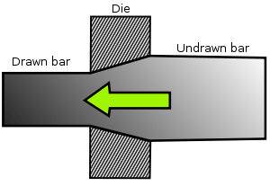
Bar, tube, and wire drawing all work upon the same principle: the starting stock drawn through a die to reduce the diameter and increase the length. Usually the die is mounted on a draw bench. The end of the workpiece is reduced or pointed to get the end through the die. The end is then placed in grips and the rest of the workpiece is pulled through the die.[1] Steels, copper alloys, and aluminium alloys are common materials that are drawn.[4]
Drawing can also be used to produce a cold formed shaped cross-section. Cold drawn cross-sections are more precise and have a better surface finish than hot extruded parts. Inexpensive materials can be used instead of expensive alloys for strength requirements, due to work hardening.[5]
Bar drawing
Bars or rods that are drawn cannot be coiled therefore straight-pull draw benches are used. Chain drives are used to draw workpieces up to 30 m (98 ft). Hydraulic cylinders are used for shorter length workpieces.[1]
The reduction in area is usually restricted to between 20 and 50%, because greater reductions would exceed the tensile strength of the material, depending on its ductility. To achieve a certain size or shape multiple passes through progressively smaller dies or intermediate anneals may be required.[6]
The Cold Drawing Process for Steel Bars and Wire
Carbide Die Cross Section
Raw Stock: Hot rolled steel bar or rod coils are used as raw material. Because the hot rolled products are produced at elevated temperatures (1700 - 2200 Deg. F. i.e. hot rolling), they generally have a rough and scaled surface and may also exhibit variations in section and size.
Cleaning: Abrasive scale (iron oxide) on the surface of the hot rolled rough stock is removed.
Coating: The surface of the bar or coil is coated with a drawing lubricant to aid cold drawing.
Pointing: Several inches of the lead ends of the bar or coil are reduced in size by swaging or extruding so that it can pass freely through the drawing die. Note: This is done because the die opening is always smaller than the original bar or coil section size.
Cold Drawing ProcessDrawing: In this process, the material being drawn is at room temperature (i.e. Cold-Drawn). The pointed/reduced end of the bar or coil, which is smaller than the die opening, is passed through the die where it enters a gripping device of the drawing machine. The drawing machine pulls or draws the remaining unreduced section of the bar or coil through the die. The die reduces the cross section of the original bar or coil, shapes the profile of the product and increases the length of the original product.
Finished Product: The drawn product, which is referred to as Cold Drawn or Cold Finished, exhibits a bright and/or polished finish, increased mechanical properties, improved machining characteristics and precise and uniform dimensional tolerances.
Multi-Pass Drawing: The cold drawing of complex shapes/profiles may require that each bar/coil be drawn several times in order to produce the desired shape and tolerances. This process is called multi-pass drawing and involves drawing through smaller and smaller die openings. Material is generally annealed between each drawing pass to remove cold work and to increase ductility.
Annealing: This is a thermal treatment generally used to soften the material being drawn, to modify the microstructure, the mechanical properties and the machining characteristics of the steel and/or to remove internal stresses in the product. Depending on the desired characteristics of the finished product, annealing may be used before, during (between passes) or after the cold drawing operation, depending on material requirements.
Tube drawing
Tube drawing is very similar to bar drawing, except the beginning stock is a tube. It is used to decrease the diameter, improve surface finish and improve dimensional accuracy. A mandrel may or may not be used depending on the specific process used.
Wire drawing
This technique has long been used to produce flexible metal wire by drawing the material through a series of dies of decreasing size. These dies are manufactured from a number of materials, the most common being tungsten carbide and diamond.
Plastic drawing
Plastic drawing, sometimes referred to as cold drawing, is the same process as used on metal bars, but applied to plastics.[7]
Cold drawing is primarily used in manufacturing plastic fibers. The process was discovered by Julian Hill (1904–1996) in 1930 while trying to make fibers from an early polyester.[8] It is performed after the material has been "spun" into filaments; by extruding the polymer melt through pores of a spinneret. During this process, the individual polymer chains tend to somewhat align because of viscous flow. These filaments still have an amorphous structure, so they are drawn to align the fibers further, thus increasing crystallinity, tensile strength and stiffness. This is done on a draw twister machine.[8][9]
For nylon, the fiber is stretched four times its spun length. The crystals formed during drawing are held together by hydrogen bonds between the amide hydrogens of one chain and the carbonyl oxygens of another chain.[9]
See also
References
Bibliography
- Degarmo, E. Paul; Black, J T.; Kohser, Ronald A. (2003), Materials and Processes in Manufacturing (9th ed.), Wiley, ISBN 0-471-65653-4.
- Kalpakjian, Serope; Schmid, Steven R. (2006), Manufacturing Engineering and Technology (5th ed.), Upper Saddle River, NJ: Pearson Prentice Hall, ISBN 0-13-148965-8