Liquid crystal on silicon
Liquid crystal on silicon (LCoS or LCOS) is a miniaturized reflective active-matrix liquid-crystal display or "microdisplay" using a liquid crystal layer on top of a silicon backplane. It is also referred to as a spatial light modulator. LCoS was initially developed for projection televisions but is now used for wavelength selective switching, structured illumination, near-eye displays and optical pulse shaping. By way of comparison, some LCD projectors use transmissive LCD, allowing light to pass through the liquid crystal.
In a LCoS display, a CMOS chip controls the voltage on square reflective aluminium electrodes buried just below the chip surface, each controlling one pixel. For example, a chip with XGA resolution will have 1024x768 plates, each with an independently addressable voltage. Typical cells are about 1–3 centimeters square and about 2 mm thick, with pixel pitch as small as 2.79 μm.[1] A common voltage for all the pixels is supplied by a transparent conductive layer made of indium tin oxide on the cover glass.
Displays
History
General Electric first demonstrated a low-resolution LCoS display in the late 1970s.[2] Starting in the late 1990s a number of companies attempted to develop products for both near-eye and projection applications.
At the 2004 CES, Intel announced plans for the large scale production of inexpensive LCoS chips for use in flat panel displays. These plans were cancelled in October 2004. Sony has made it to market (December 2005) with the Sony-VPL-VW100 or "Ruby" projector, using SXRD, 3 LCoS chips each with a native resolution of 1920×1080, with a stated contrast ratio of 15,000:1 using a dynamic iris.
Whilst LCoS technology was initially touted as a technology to enable large-screen, high-definition, rear-projection televisions with very high picture quality at relatively low cost, the development of large-screen LCD and plasma flat panel displays obsoleted rear projection televisions. As of October 2013, LCoS-based rear-projection televisions are no longer produced.
Commercial implementations of LCoS technology include Sony's Silicon X-tal Reflective Display (SXRD) and JVC's Digital Direct Drive Image Light Amplifier (D-ILA/). Every company which produces and markets LCoS rear-projection televisions uses three-panel LCoS technology,. Sony and JVC both produce and market front-projection displays that use three LCoS panels. Canon too, with XEED projectors.
Developers and manufacturers who have left the LCoS imaging market include: Intel, Philips, MicroDisplay Corporation (the only company to successfully bring to market a single-panel LCoS television[3] ), S-Vision, Colorado Microdisplay, Spatialight, Syntax-Brillian.
Display system architectures
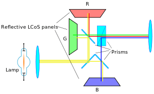
There are two broad categories of LCoS displays: three-panel and single-panel. In three-panel designs, there is one display chip per color, and the images are combined optically. In single-panel designs, one display chip shows the red, green, and blue components in succession with the observer's eyes relied upon to combine the color stream. As each color is presented, a color wheel (or an RGB LED array) illuminates the display with only red, green or blue light. If the frequency of the color fields is lower than about 540 Hz, an effect called color breakup is seen, where false colors are briefly perceived when either the image or the observer's eye is in motion. While less expensive; single-panel projectors require higher-speed display elements to process all three colors during a single frame time, and the need to avoid color breakup makes further demands on the speed of the display technology.
Three-panel designs
The white light is separated into three components (red, green and blue) and then combined back after modulation by the 3 LCoS devices. The light is additionally polarized by beam splitters.
One-panel designs
Both Toshiba's and Intel's single-panel LCOS display program were discontinued in 2004 before any units reached final-stage prototype.[4] There were single-panel LCoS displays in production: One by Philips and one by Microdisplay Corporation. Forth Dimension Displays continues to offer a Ferroelectric LCoS display technology (known as Time Domain Imaging) available in QXGA, SXGA and WXGA resolutions which today is used for high resolution near-eye applications such as Training & Simulation, structured light pattern projection for AOI. Micron's FLCoS technology is another single panel RGB solution used in pico-projectors, and near-eye display applications.
Pico projectors, near-eye and head-mounted displays
Whilst initially developed for large-screen projectors, LCoS displays have found a consumer niche in the area of pico-projectors, where their small size and low power consumption are well-matched to the constraints of such devices.
LCoS devices are also used in near-eye applications such as electronic viewfinders for digital cameras, film cameras, and head-mounted displays (HMDs). These devices are made using ferroelectric liquid crystals (so the technology is named FLCoS) which are inherently faster than other types of liquid crystals to produce high quality images.[5] Google's initial foray into wearable computing, Google glass,[6] also uses a near-eye LCoS display based on an LCoS chip from Himax Technologies.[7]
Wavelength-selective switches
LCoS is particularly attractive as a switching mechanism in a wavelength-selective switch (WSS). LCoS-based WSS were initially developed by Australian company Engana,[8] now part of Finisar.[9] The LCoS can be employed to control the phase of light at each pixel to produce beam-steering[10] where the large number of pixels allow a near continuous addressing capability. Typically, a large number of phase steps are used to create a highly efficient, low-insertion loss switch shown. This simple optical design incorporates polarisation diversity, control of mode size and a 4-f wavelength optical imaging in the dispersive axis of the LCoS providing integrated switching and optical power control.[11]
In operation, the light passes from a fibre array through the polarisation imaging optics which separates physically and aligns orthogonal polarisation states to be in the high efficiency s-polarisation state of the diffraction grating. The input light from a chosen fibre of the array is reflected from the imaging mirror and then angularly dispersed by the grating which is at near Littrow incidence, reflecting the light back to the imaging optics which directs each channel to a different portion of the LCoS. The path for each wavelength is then retraced upon reflection from the LCoS, with the beam-steering image applied on the LCOS directing the light to a particular port of the fibre array. As the wavelength channels are separated on the LCoS the switching of each wavelength is independent of all others and can be switched without interfering with the light on other channels. There are many different algorithms that can be implemented to achieve a given coupling between ports including less efficient "images" for attenuation or power splitting.
WSS based on MEMS[12] and/or liquid crystal[13] technologies allocate a single switching element (pixel) to each channel which means the bandwidth and centre frequency of each channel are fixed at the time of manufacture and cannot be changed in service. In addition, many designs of first-generation WSS (particularly those based on MEMs technology) show pronounced dips in the transmission spectrum between each channel due to the limited spectral ‘fill factor’ inherent in these designs. This prevents the simple concatenation of adjacent channels to create a single broader channel.
LCoS-based WSS, however, permit dynamic control of channel centre frequency and bandwidth through on-the-fly modification of the pixel arrays via embedded software. The degree of control of channel parameters can be very fine-grained, with independent control of the centre frequency and either upper- or lower-band-edge of a channel with better than 1 GHz resolution possible. This is advantageous from a manufacturability perspective, with different channel plans being able to be created from a single platform and even different operating bands (such as C and L) being able to use an identical switch matrix. Additionally, it is possible to take advantage of this ability to reconfigure channels while the device is operating. Products have been introduced allowing switching between 50 GHz channels and 100 GHz channels, or a mix of channels, without introducing any errors or "hits" to the existing traffic. More recently, this has been extended to support the whole concept of Flexible or Elastic networks under ITU G.654.2 through products such as Finisar's Flexgrid™ WSS.
Other LCoS applications
Optical pulse shaping
The ability of an LCoS-based WSS to independently control both the amplitude and phase of the transmitted signal leads to the more general ability to manipulate the amplitude and/or phase of an optical pulse through a process known as Fourier-domain pulse shaping.[14] This process requires full characterisation of the input pulse in both the time and spectral domains.
As an example, an LCoS-based Programmable Optical Processor(POP) has been used to broaden a mode-locked laser output into a 20 nm supercontinuum source whilst a second such device was used to compress the output to 400 fs, transform-limited pulses.[15] Passive mode-locking of fiber lasers has been demonstrated at high repetition rates, but inclusion of an LCoS-based POP allowed the phase content of the spectrum to be changed to flip the pulse train of a passively mode-locked laser from bright to dark pulses.[16] A similar approach uses spectral shaping of optical frequency combs to create multiple pulse trains. For example, a 10 GHz optical frequency comb was shaped by the POP to generate dark parabolic pulses and Gaussian pulses, at 1540 nm and 1560 nm, respectively.[17]
Light structuring
Structured light using a fast ferroelectric LCoS is used in 3D-superresolution microscopy techniques and in fringe projection for 3D-automated optical inspection.
Modal switching in space division multiplexed optical communications systems
One of the interesting applications of LCoS is the ability to transform between modes of few-moded optical fibers[18] which have been proposed as the basis of higher capacity transmission systems in the future. Similarly LCoS has been used to steer light into selected cores of multicore fiber transmission systems, again as a type of Space Division Multiplexing.
Tunable lasers
LCoS has been used as a filtering technique, and hence a tuning mechanism, for both semiconductor diode and fibre lasers.[19]
References
- ↑ Compound Photonics. "Products Compound Photonics". Retrieved 2014-10-13.
- ↑ Armitage, D. et al. (2006) Introduction to Microdisplays, Wiley, ISBN 978-0-470-85281-1
- ↑ Chin, Spencer. "MicroDisplay LCoS panel comes in under an inch". EE Times.
- ↑ Hachman, Mark. "Update: Intel Cancels LCOS Chip Plans". 415.992.5910. Extreme Tech. Retrieved June 17, 2011.
- ↑ Collings, N. (2011). "The Applications and Technology of Phase-Only Liquid Crystal on Silicon Devices". IEEE Journal of Display Technology. 7 (3): 112–119. doi:10.1109/JDT.2010.2049337.
- ↑ Google glass. google.com
- ↑ Guttag, Karl (2013-03-11) Google Glass Is Using Field Sequential Color (FSC) LCOS (Likely Himax). kguttag.com
- ↑ Baxter, G. et al. (2006) "Highly Programmable Wavelength Selective Switch Based on Liquid Crystal on ," in Optical Fiber Communication Conference, 2006 and the 2006 National Fiber Optic Engineers Conference.
- ↑ ROADMs & Wavelength Management. finisar.com
- ↑ Johnson, K. M. (1993). "Smart spatial light modulators using liquid crystals on silicon". IEEE J. Quant. Electron. 29: 699. doi:10.1109/3.199323.
- ↑ Kaminov, Li and Wilner (ed.). "Ch. 16". Optical Fiber Telecommunications VIA. Academic Press. ISBN 978-0-12-396958-3.
- ↑ Marom, D. M. et al. (2002) "Wavelength-selective 1×4 switch for 128 WDM channels at 50 GHz spacing," in Proc. Optical Fiber Communications), Anaheim, CA, Postdeadline Paper FB7, pp. FB7-1–FB7-3
- ↑ Kondis, J. et al. (2001) "Liquid crystals in bulk optics-based DWDM optical switches and spectral equalizers," pp. 292–293 in Proc. LEOS 2001, Piscataway, NJ.
- ↑ Weiner, A.M. (2000). "Femtosecond pulse shaping using spatial light modulators" (PDF). Rev. Sci. Instrum. 71 (5): 1929–1960. doi:10.1063/1.1150614.
- ↑ A. M. Clarke, D. G. Williams, M. A. F. Roelens, M. R. E. Lamont, and B. J. Eggleton, "Parabolic pulse shaping for enhanced continuum generation using an LCoS-based wavelength selective switch," in 14th OptoElectronics and Communications Conference (OECC) 2009.
- ↑ Schroeder, Jochen B. (2010). "Dark and Bright Pulse Passive Mode-locked Laser with In-cavity Pulse-shaper". Optics Express. 18 (22): 22715–22721. doi:10.1364/OE.18.022715. PMID 21164610.
- ↑ Ng, T. T. et al. (2009) "Complete Temporal Optical Fourier Transformations Using Dark Parabolic Pulses," in 35th European Conference on Optical Communication.
- ↑ Salsi, Massimiliano; Koebele, Clemens; Sperti, Donato; Tran, Patrice; Mardoyan, Haik; Brindel, Patrick; Bigo, Sébastien; Boutin, Aurélien; Verluise, Frédéric; Sillard, Pierre; Astruc, Marianne; Provost, Lionel; Charlet, Gabriel (2012). "Mode-Division Multiplexing of 2×100 Gb/s Channels Using an LCOS-Based Spatial Modulator". Journal of Lightwave Technology. 30 (4): 618. doi:10.1109/JLT.2011.2178394.
- ↑ Xiao, Feng (2009). "Opto-VLSI-based Tunable Single-mode Fiber Laser". Optics Express. 17 (21): 18676–18680. doi:10.1364/OE.17.018676. PMID 20372600.
External links
- Biever, Celeste. 'Intel inside' comes to flat panel TVs (January 9, 2004 – No longer planned for development) New Scientist
- Everything You Need to Know About TV Technologies from Hardware Secrets