Galvanometer

A galvanometer is an electromechanical instrument for detecting and measuring electric current. The most common use of galvanometers was as analog measuring instruments, called ammeters, used to measure the direct current (flow of electric charge) through an electric circuit. A galvanometer works as an actuator, by producing a rotary deflection (of a "pointer"), in response to electric current flowing through a coil in a constant magnetic field.
Galvanometers developed from the observation that the needle of a magnetic compass is deflected near a wire that has electric current flowing through it, first described by Hans Oersted in 1820. They were the first instruments used to detect and measure small amounts of electric currents. The name comes from the Italian electricity researcher Luigi Galvani, who in 1791 discovered the principle of the frog galvanoscope – that electric current would make the legs of a dead frog jerk.
Sensitive galvanometers have been essential for the development of science and technology in many fields. For example, they enabled long range communication through submarine cables, such as the earliest Transatlantic telegraph cables, and were essential to discovering the electrical activity of the heart and brain, by their fine measurements of current.
Galvanometers also had widespread use as the visualising part in other kinds of analog meters, for example in light meters, VU meters, etc., where they were used to measure and display the output of other sensors. Today the main type of galvanometer mechanism, still in use, is the moving coil, D'Arsonval/Weston type.
Operation
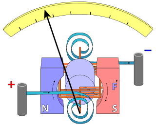
Modern galvanometers, of the D'Arsonval/Weston type, are constructed with a small pivoting coil of wire in the field of a permanent magnet. The coil is attached to a thin pointer that traverses a calibrated scale. A tiny torsion spring pulls the coil and pointer to the zero position.
When a direct current (DC) flows through the coil, the coil generates a magnetic field. This field acts against the permanent magnet. The coil twists, pushing against the spring, and moves the pointer. The hand points at a scale indicating the electric current. Careful design of the pole pieces ensures that the magnetic field is uniform, so that the angular deflection of the pointer is proportional to the current. A useful meter generally contains provision for damping the mechanical resonance of the moving coil and pointer, so that the pointer settles quickly to its position without oscillation.
The basic sensitivity of a meter might be, for instance, 100 microamperes full scale (with a voltage drop of, say, 50 millivolts at full current). Such meters are often calibrated to read some other quantity that can be converted to a current of that magnitude. The use of current dividers, often called shunts, allows a meter to be calibrated to measure larger currents. A meter can be calibrated as a DC voltmeter if the resistance of the coil is known by calculating the voltage required to generate a full scale current. A meter can be configured to read other voltages by putting it in a voltage divider circuit. This is generally done by placing a resistor in series with the meter coil. A meter can be used to read resistance by placing it in series with a known voltage (a battery) and an adjustable resistor. In a preparatory step, the circuit is completed and the resistor adjusted to produce full scale deflection. When an unknown resistor is placed in series in the circuit the current will be less than full scale and an appropriately calibrated scale can display the value of the previously unknown resistor.
These capabilities to translate different kinds of electric quantities, in to pointer movements, make the galvanometer ideal for turning output of other sensors that outputs electricity (in some form or another), into something that can be read by a human.
Because the pointer of the meter is usually a small distance above the scale of the meter, parallax error can occur when the operator attempts to read the scale line that "lines up" with the pointer. To counter this, some meters include a mirror along the markings of the principal scale. The accuracy of the reading from a mirrored scale is improved by positioning one's head while reading the scale so that the pointer and the reflection of the pointer are aligned; at this point, the operator's eye must be directly above the pointer and any parallax error has been minimized.
Uses

Probably the largest use of galvanometers was of the D'Arsonval/Weston type used in analog meters in electronic equipment. Since the 1980s, galvanometer-type analog meter movements have been displaced by analog to digital converters (ADCs) for many uses. A digital panel meter (DPM) contains an analog to digital converter and numeric display. The advantages of a digital instrument are higher precision and accuracy, but factors such as power consumption or cost may still favour application of analog meter movements.
Modern uses
Most modern uses for the galvanometer mechanism are in positioning and control systems. Galvanometer mechanisms are divided into moving magnet and moving coil galvanometers; in addition, they are divided into closed-loop and open-loop - or resonant - types.
Mirror galvanometer systems are used as beam positioning or beam steering elements in laser scanning systems. For example, for material processing with high-power lasers, closed loop mirror galvanometer mechanisms are used with servo control systems. These are typically high power galvanometers and the newest galvanometers designed for beam steering applications can have frequency responses over 10 kHz with appropriate servo technology. Closed-loop mirror galvanometers are also used in similar ways in stereolithography, laser sintering, laser engraving, laser beam welding, laser TVs, laser displays and in imaging applications such as retinal scanning with Optical Coherence Tomography (OCT). Almost all of these galvanometers are of the moving magnet type.
Open loop, or resonant mirror galvanometers, are mainly used in some types of laser-based bar-code scanners, printing machines, imaging applications, military applications and space systems. Their non-lubricated bearings are especially of interest in applications that require functioning in a high vacuum.

Moving coil type galvanometer mechanisms (called 'voice coils' by hard disk manufacturers) are used for controlling the head positioning servos in hard disk drives and CD/DVD players, in order to keep mass (and thus access times), as low as possible.
Past uses
A major early use for galvanometers was for finding faults in telecommunications cables. They were superseded in this application late in the 20th century by time-domain reflectometers.
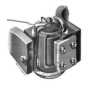
Galvanometer mechanisms were also used to get readings from photoresistors in the metering mechanisms of film cameras (as seen in the adjacent image).
In analog strip chart recorders such as used in electrocardiographs, electroencephalographs and polygraphs, galvanometer mechanisms were used to position the pen. Strip chart recorders with galvanometer driven pens may have a full scale frequency response of 100 Hz and several centimeters of deflection.
History
.jpg)
The deflection of a magnetic compass needle by current in a wire was first described by Hans Oersted in 1820. The phenomenon was studied both for its own sake and as a means of measuring electric current. The earliest galvanometer was reported by Johann Schweigger at the University of Halle on 16 September 1820. André-Marie Ampère also contributed to its development. Early designs increased the effect of the magnetic field generated by the current by using multiple turns of wire. The instruments were at first called "multipliers" due to this common design feature. The term "galvanometer," in common use by 1836, was derived from the surname of Italian electricity researcher Luigi Galvani, who in 1791 discovered that electric current would make a dead frog's leg jerk.
Originally, the instruments relied on the Earth's magnetic field to provide the restoring force for the compass needle. These were called "tangent" galvanometers and had to be oriented before use. Later instruments of the "astatic" type used opposing magnets to become independent of the Earth's field and would operate in any orientation. The most sensitive form, the Thomson or mirror galvanometer, was patented in 1858 by William Thomson (Lord Kelvin) as an improvement of an earlier design invented in 1826 by Johann Christian Poggendorff. Thomson's design, was able to detect very rapid current changes, by using small magnets attached to a lightweight mirror, suspended by a thread, instead of a compass needle. The deflection of a light beam on the mirror greatly magnified the deflection induced by small currents. Alternatively, the deflection of the suspended magnets could be observed directly through a microscope.
The ability to measure quantitatively voltage and current allowed Georg Ohm to formulate that – the voltage across a conductor is directly proportional to the current through it – Ohm's Law.
The early moving-magnet form of galvanometer had the disadvantage that it was affected by any magnets or iron masses near it, and its deflection was not linearly proportional to the current. In 1882 Jacques-Arsène d'Arsonval and Marcel Deprez developed a form with a stationary permanent magnet and a moving coil of wire, suspended by fine wires which provided both an electrical connection to the coil and the restoring torque to return to the zero position. An iron tube between the magnet's pole pieces defined a circular gap through which the coil rotated. This gap produced a consistent, radial magnetic field across the coil, giving a linear response throughout the instrument's range. A mirror attached to the coil deflected a beam of light to indicate the coil position. The concentrated magnetic field and delicate suspension made these instruments sensitive; d'Arsonval's initial instrument could detect ten microamperes.[1]
Edward Weston extensively improved the design. He replaced the fine wire suspension with a pivot, and provided restoring torque and electrical connections through spiral springs rather like those of a wristwatch balance wheel hairspring. He developed a method of stabilizing the magnetic field of the permanent magnet, so the instrument would have consistent accuracy over time. He replaced the light beam and mirror with a knife-edge pointer that could be read directly. A mirror under the pointer, in the same plane as the scale, eliminated parallax observation error. To maintain the field strength, Weston's design used a very narrow circumferential slot through which the coil moved, with a minimal air-gap. This improved linearity of pointer deflection with respect to coil current. Finally, the coil was wound on a light-weight form made of conductive metal, which acted as a damper. By 1888, Edward Weston had patented and brought out a commercial form of this instrument, which became a standard electrical equipment component. It was known as a "portable" instrument because it was affected very little by mounting position or by transporting it from place to place. This design is almost universally used in moving-coil meters today.
Initially laboratory instruments relying on the Earth's own magnetic field to provide restoring force for the pointer, galvanometers were developed into compact, rugged, sensitive portable instruments essential to the development of electro-technology.
Types
Some galvanometers use a solid pointer on a scale to show measurements; other very sensitive types use a miniature mirror and a beam of light to provide mechanical amplification of low-level signals.
Tangent galvanometer
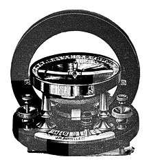
A tangent galvanometer is an early measuring instrument used for the measurement of electric current. It works by using a compass needle to compare a magnetic field generated by the unknown current to the magnetic field of the Earth. It gets its name from its operating principle, the tangent law of magnetism, which states that the tangent of the angle a compass needle makes is proportional to the ratio of the strengths of the two perpendicular magnetic fields. It was first described by Claude Pouillet in 1837.
A tangent galvanometer consists of a coil of insulated copper wire wound on a circular non-magnetic frame. The frame is mounted vertically on a horizontal base provided with levelling screws. The coil can be rotated on a vertical axis passing through its centre. A compass box is mounted horizontally at the centre of a circular scale. It consists of a tiny, powerful magnetic needle pivoted at the centre of the coil. The magnetic needle is free to rotate in the horizontal plane. The circular scale is divided into four quadrants. Each quadrant is graduated from 0° to 90°. A long thin aluminium pointer is attached to the needle at its centre and at right angle to it. To avoid errors due to parallax, a plane mirror is mounted below the compass needle.
In operation, the instrument is first rotated until the magnetic field of the Earth, indicated by the compass needle, is parallel with the plane of the coil. Then the unknown current is applied to the coil. This creates a second magnetic field on the axis of the coil, perpendicular to the Earth's magnetic field. The compass needle responds to the vector sum of the two fields, and deflects to an angle equal to the tangent of the ratio of the two fields. From the angle read from the compass's scale, the current could be found from a table.[2] The current supply wires have to be wound in a small helix, like a pig's tail, otherwise the field due to the wire will affect the compass needle and an incorrect reading will be obtained.
Theory
The galvanometer is oriented so that the plane of the coil is vertical and aligned along parallel to the horizontal component BH of the Earth's magnetic field (i.e. parallel to the local "magnetic meridian"). When an electric current flows through the galvanometer coil, a second magnetic field B is created. At the center of the coil, where the compass needle is located, the coil's field is perpendicular to the plane of the coil. The magnitude of the coil's field is:

where I is the current in amperes, n is the number of turns of the coil and r is the radius of the coil. These two perpendicular magnetic fields add vectorially, and the compass needle points along the direction of their resultant BH+B. The current in the coil causes the compass needle to rotate by an angle θ:

From tangent law, B = BH tan θ, i.e.

or

or I = K tan θ, where K is called the Reduction Factor of the tangent galvanometer.
One problem with the tangent galvanometer is that its resolution degrades at both high currents and low currents. The maximum resolution is obtained when the value of θ is 45°. When the value of θ is close to 0° or 90°, a large percentage change in the current will only move the needle a few degrees.
Geomagnetic field measurement
A tangent galvanometer can also be used to measure the magnitude of the horizontal component of the geomagnetic field. When used in this way, a low-voltage power source, such as a battery, is connected in series with a rheostat, the galvanometer, and an ammeter. The galvanometer is first aligned so that the coil is parallel to the geomagnetic field, whose direction is indicated by the compass when there is no current through the coils. The battery is then connected and the rheostat is adjusted until the compass needle deflects 45 degrees from the geomagnetic field, indicating that the magnitude of the magnetic field at the center of the coil is the same as that of the horizontal component of the geomagnetic field. This field strength can be calculated from the current as measured by the ammeter, the number of turns of the coil, and the radius of the coils.
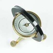
Astatic galvanometer

Unlike a compass-needle galvanometer, the astatic galvanometer has two magnetic needles parallel to each other, but with the magnetic poles reversed. The needle assembly is suspended by a silk thread, and has no net magnetic dipole moment. It is not affected by the earth's magnetic field. The lower needle is inside the current sensing coils and is deflected by the magnetic field created by the passing current.
The astatic galvanometer was developed by Leopoldo Nobili in 1825.[3]
Mirror galvanometer
To get a higher level of precision, for extremely sensitive measuring equipment, the mirror galvanometer substituted the pointer with a lightweight mirror. Thus a beam of light, reflected from the mirror, acted as a long mass-less pointer. This kind of galvanometer were for example used as the receivers in early trans-Atlantic telegraph systems. In a device called an oscillograph, the moving beam of light was used, to produce graphs of current versus time, by recording measurements on photographic film. The string galvanometer was a type of mirror galvanometer so sensitive that it was used to make the first electrocardiogram of the electrical activity of the human heart.
Ballistic galvanometer
A ballistic galvanometer is a type of sensitive galvanometer for measuring the quantity of charge discharged through it. In reality it is an integrator, unlike a current-measuring galvanometer, the moving part has a large moment of inertia that gives it a long oscillation period. It can be either of the moving coil or moving magnet type, commonly it is a mirror galvanometer.
See also
References
- ↑ Joseph F. Keithley The story of electrical and magnetic measurements: from 500 B.C. to the 1940s, John Wiley and Sons, 1999 ISBN 0-7803-1193-0, pp. 196-198
- ↑ Greenslade, Jr., Thomas B. "Tangent Galvanometer". Kenyon College. Retrieved 26 April 2016.
- ↑ Greenslade, Thomas. "Instruments for Natural Philosophy — Astatic Galvanometer". Kenyon College. Retrieved 2010-12-19.
External links
| Wikimedia Commons has media related to Galvanometers. |
- Galvanometer - Interactive Java Tutorial National High Magnetic Field Laboratory
- Selection of historic galvanometer in the Virtual Laboratory of the Max Planck Institute for the History of Science