Cryocooler
A Cryocooler is a standalone cooler, usually of table-top size. It is used to cool some particular application to cryogenic temperatures. A recent review is given by Radebaugh.[1] The present article deals with various types of cryocoolers and is partly based on a paper by De Waele.[2]
Ideal heat exchangers and regenerators
Heat exchangers are important components of all cryocoolers. Ideal heat exchangers have no flow resistance and the exit gas temperature is the same as the (fixed) body temperature TX of the heat exchanger. Note that even a perfect heat exchanger will not affect the entrance temperature Ti of the gas. This leads to losses.
An important component of refrigerators, operating with oscillatory flows, is the regenerator. A regenerator consists of a matrix of a solid porous material, such as granular particles or metal sieves, through which gas flows back and forth. Periodically heat is stored and released by the material. The heat contact with the gas must be good and the flow resistance of the matrix must be low. These are conflicting requirements. The thermodynamic and hydrodynamic properties of regenerators are very complicated, so one usually makes simplifying models. In its most extreme form an ideal regenerator has the following properties:
- large volumetric heat capacity of the material;
- perfect heat contact between gas and matrix;
- zero flow resistance of the matrix;
- zero porosity (this is the volume fraction of the gas);
- zero thermal conductivity in the flow direction;
- the gas is ideal.
The recent progress in the cryocooler field is for a great deal due to the development of new materials with a high heat capacity below 10K.[3]
Stirling refrigerators

The basic type of Stirling-type cooler is depicted in fig. 1. From left to right it consists of a piston, a compression space, and heat exchanger (all at ambient temperature Ta), a regenerator, and a heat exchanger, expansion space, and a piston (all at the low temperature TL). Left and right the thermal contact with the surroundings at the temperatures Ta and TL is supposed to be perfect so that the compression and expansion are isothermal. The work, performed during the expansion, is used to reduce the total input power. Usually helium is the working fluid.

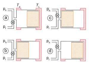
The cooling cycle is split in 4 steps as depicted in fig. 2. The cycle starts when the two pistons are in their most left positions:
- From a to b. The warm piston moves to the right while the cold piston is fixed. The compression at the hot end is isothermal (by definition), so heat Qa is given off to the surroundings at ambient temperature Ta.
- From b to c. The two pistons move to the right. The volume between the two pistons is kept constant. The hot gas enters the regenerator with temperature Ta and leaves it with temperature TL. The gas gives off heat to the regenerator material.
- From c to d. The cold piston moves to the right while the warm piston is fixed. The expansion is isothermal and heat QL is taken up. This is the useful cooling power.
- From d to a. The two pistons move to the left while the total volume remains constant. The gas enters the regenerator with low temperature TL and leaves it with high temperature Ta so heat is taken up from the regenerator material. At the end of this step the state of the cooler is the same as in the beginning.

In the pV diagram (fig. 3) the corresponding cycle consists of two isotherms and two isochores. The volume V is the volume between the two pistons. In practice the cycle is not divided in discrete steps as described above. Usually the motions of both pistons are driven by a common rotary axes which makes the motions harmonic. The phase difference between the motions of the two pistons is about 90°. In the ideal case the cycle is reversible so the COP (the ratio of the cooling power and the input power) is equal to the Carnot COP given by TL/(Ta-TL).
It is not so practical to have a cold piston, as described above, so, in many cases, a displacer is used instead of the cold piston. A displacer is a solid body which moves back and forth in the cold head driving the gas back and forth between the warm and the cold end of the cold head via the regenerator. No work is required to move the displacer since, ideally there is no pressure drop over it. Typically its motion is 90 degrees out of phase with the piston. In the ideal case the COP also equals to the Carnot COP.
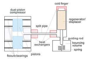
Another type of Stirling cooler is the split-pair type (fig. 4), consisting of a compressor, a split pipe, and a cold finger. Usually there are two pistons moving in opposite directions driven by AC magnetic fields (as in loudspeakers). The pistons can be suspended by so-called flexure bearings. They provide stiffness in the radial direction and flexibility in the axial direction. The pistons and the compressor casing don't touch so no lubricants are needed and there is no wear. The regenerator in the cold finger is suspended by a spring. The cooler operates at a frequency near the resonance frequency of the mass-spring system of the cold finger.
GM-refrigerators

Gifford-McMahon (GM) coolers[4] have found widespread application in many low-temperature systems; e.g., in MRI and cryopumps. Fig. 5 is a schematic diagram. Helium at pressures in the 10 to 30 bar range is the working fluid. The cold head contains a compression and expansion space, a regenerator, and a displacer. Usually the regenerator and the displacer are combined in one body. The pressure variations in the cold head are obtained by connecting it periodically to the high- and low-pressure sides of a compressor by a rotating valve. Its position is synchronized with the motion of the displacer. During the opening and closing of the valves irreversible processes take place, so GM-coolers have intrinsic losses. This is a clear disadvantage of this type of cooler. The advantage is that the cycle frequencies of the compressor and the displacer are uncoupled so that the compressor can run at power-line frequency (50 or 60 Hz) while the cycle of the cold head is 1 Hz. In this way the swept volume of the compressor can be 50 (60) times smaller than of the cooler. Basically (cheap) compressors of domestic refrigerators can be used, but one must prevent overheating of the compressor as it is not designed for helium. One must also prevent oil vapor from entering the regenerator by high-quality purification traps.
The cycle can be divided in four steps, with fig. 6, as follows: the cycle starts with the low-pressure (LP) valve closed, the high-pressure (HP) valve open, and the displacer all the way to the right (so in the cold region). All the gas is at room temperature.
- From a to b. The displacer moves to the left while the cold head is connected to the HP side of the compressor. The gas passes the regenerator entering the regenerator at ambient temperature Ta and leaving it with temperature TL. Heat is released by the gas to the regenerator material.
- From b to c. The HP valve is closed and the LP valve opened with fixed position of the displacer. Part of the gas flows through the regenerator to the LP side of the compressor. The gas expands. The expansion is isothermal so heat is taken up from the application. This is where the useful cooling power is produced.
- From c to d. The displacer moves to the right with the cold head connected to the LP side of the compressor forcing the cold gas to pass the regenerator, while taking up heat from the regenerator.
- From d to a. The LP valve is closed and the HP valve opened with fixed position of the displacer. The gas, now in the hot end of the cold head, is compressed and heat is released to the surroundings. In the end of this step we are back in position a.
Pulse-tube refrigerators

The pulse tube refrigerator is treated in a separate article. For completeness a so-called Stirling-type single-orifice PTR is represented schematically in fig. 7. From left to right it consists of: a piston which moves back and forth; a heat exchanger X₁ (after cooler) where heat is released at room temperature (Ta) to cooling water or to the surroundings; a regenerator; a heat exchanger XL at low temperature (TL) where heat is absorbed from the application; a tube, often called the pulse tube; a heat exchanger X₃ to room temperature (Ta); a flow resistance (orifice); a buffer volume, in which the pressure pB is practically constant.
Joule-Thomson cooler

The Joule-Thomson (JT) cooler was invented by Carl von Linde and William Hampson so it is also called the Linde-Hampson cooler. Basically it is a very simple type of cooler which is widely applied as cryocooler or as the (final stage) of liquefactors. It can easily be miniaturized, but it is also used on a very large scale in the liquefaction of natural gas. A schematic diagram of a JT liquefier is given in fig. 8. It consists of a compressor, a counterflow heat exchanger, a JT valve, and a reservoir. In fig. 8, the pressures and temperatures refer to the case of a nitrogen liquefier. At the inlet of the compressor the gas is at room temperature (300 K) and a pressure of 1 bar (point a). The compression heat is removed by cooling water. After compression the gas temperature is ambient temperature (300 K) and the pressure is 200 bar (point b). Next it enters the warm (high-pressure) side of the counterflow heat exchanger where it is precooled. It leaves the exchanger at point c. After the JT expansion, point d, it has a temperature of 77.36 K and a pressure of 1 bar. The liquid fraction is x. The liquid leaves the system at the bottom of the reservoir (point e) and the gas (fraction 1 − x) flows into the cold (low-pressure) side of the counterflow heat exchanger (point f). It leaves the heat exchanger at room temperature (point a). In order to keep the system in the steady state gas is supplied to compensate for the liquid fraction x that has been removed.
When used as a cryocooler it is preferable to use gas mixtures instead of pure nitrogen. In this way the efficiency is improved and the high pressure is much lower than 200 bar.
See also
- Cryogenic processor
- Adiabatic demagnetization refrigerator
- Dilution refrigerator
- Hampson-Linde cycle
- Stirling engine (Stirling cryocooler)
- Entropy production
References
- ↑ R. Radebaugh, J. Phys.: Condens. Matter, Vol.21, 164219 (2009)
- ↑ A.T.A.M. de Waele, Basic operation of cryocoolers and related thermal machines, Review article, Journal of Low Temperature Physics, Vol.164, pp. 179-236, (2011), DOI: 10.1007/s10909-011-0373-x.
- ↑ T. Kuriyama, R. Hakamada, H. Nakagome, Y. Tokai, M. Sahashi, R. Li, O. Yoshida, K. Matsumoto, and T. Hashimoto, Advances in Cryogenic Engineering 35B, 1261 (1990)
- ↑ W.E. Gifford and R.C. Longsworth, Advances in Cryogenic Engineering 11, 171 (1966)
|