Coupling rod
A coupling rod or side rod connects the driving wheels of a locomotive. Steam locomotives in particular usually have them, but some diesel and electric locomotives, especially older ones and shunters, also have them. The coupling rods transfer the power to all driving wheels.
Development
Locomotion No 1 was the first locomotive to employ coupling rods rather than chains. In the 1930s reliable roller bearing coupling rods were developed.[1]
Allowance for Vertical Motion

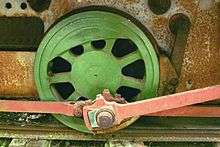
In general, all railroad vehicles have spring suspension; without springs, irregularities in the track could lift wheels off the rail and cause impact damage to both rails and vehicles. Driving wheels are typically mounted so that they have around 1 inch (2.5 cm) of vertical motion. When there are only 2 coupled axles, this range of motion places only slight stress on the crank pins. With more axles, however, provision must be made to allow each axle to move vertically independently of the others without bending the rods. This may be done by hinging the side rod at each intermediate crank pin, either using the pin itself as a hinge pin,[2][3] or adding a hinge joint adjacent to the pin, as shown in the illustration.
An alternative is to use a side rod that spans multiple axles with a scotch yoke used at each intermediate axle. This approach was quite common when side rods were used to link a jackshaft to 2 or more driving wheels on electric locomotives and some early internal combustion locomotives. The Swiss Ce 6/8II Crocodile locomotive is a prominent example, but there were others.[4][5][6]
Balancing

The coupling rod's off-center attachment to the crank pin of the driving wheel inevitably creates an eccentric movement and vibration when in motion. To compensate for this, the driving wheels of an inside-frame locomotive always had built-in counterweights to offset the angular momentum of the coupling rods, as shown in the figures above. On outside-frame locomotives, the counterweight could be on the driving wheel itself, or it could be on the crank outside the frame, as shown in the adjacent figure.
Where the motion of the side-rods is purely circular, as on locomotives driven by jackshafts or geared transmission to one driver, counterweights can balance essentially all of the motion of the side rods. Where part of the motion is non-circular, for example, the horizontal motion of a piston rod, counterweights on the wheels or drive axles cannot be made to balance the entire assembly perfectly. On a driving wheel supporting both side-rods and the connecting rod to a piston, the counterweight needed to balance the horizontal motion of the piston and connecting rod would be heavier than the counterweight needed to balance the vertical weight of the rods. As a result, a counterweight chosen to minimize the total vibration will not minimize the vertical component of the vibration.
The vertical component of the vibration that could not be eliminated because of the weight needed to balance the pistons is called hammering. This is destructive to both the locomotive and the roadbed. In some locomotives, this hammering can be so intense that at speed, the drivers alternately jump from the rail head, then slam down hard on the rails as the wheels complete their rotation. Unfortunately, hammering is inherent to conventional two-cylinder piston-driven steam locomotives and that is one of the several reasons they have been retired from service.
Materials
Initially, coupling rods were made of steel. As technology progressed and better materials became available, the connecting rods were manufactured of lighter and stronger alloys, which in turn permitted smaller counterweights and also reduced hammering.
References
- ↑ Tracy V. Buckwalter, Locomotive Drive, U.S. Patent 1,951,126, granted Mar. 13, 1934.
- ↑ Robert Humble, Connecting-Rod, U.S. Patent 391,148, granted Oct. 16, 1888.
- ↑ William G. Knight, Locomotive Driving Rod Connection, U.S. Patent 1,807,217, granted May 18, 1931.
- ↑ Archibald H. Ehle, Internal-Combustion Locomotive, U.S. Patent 951,062, granted Mar. 1, 1910
- ↑ General Construction, Baldwin Gasoline Industrial Locomotives Baldwin Locomotive Works Record, No. 74, 1913; pages 7-9. The reason for the scotch yoke is given explicitly on page 8.
- ↑ Norman W. Storer, Electric Locomotive, U.S. Patent 991,038, granted May 2, 1911.
See also
| Wikimedia Commons has media related to Locomotives with coupling rod. |