Gangway connection
A corridor connection (or gangway connection) is a flexible connector fitted to the end of a railway coach to enable passage from one coach to another without falling out of the train.
Origins: Coaches in British and American railways
The London and North Western Railway (LNWR) was the first British railway to provide passengers with the means to move from one coach to another whilst the train was in motion. In 1869 the LNWR built a pair of saloons for the use of Queen Victoria; these had six-wheel underframes (the bogie coach did not appear in Britain until 1874), and the gangway was fitted to only one end of each coach. The Queen preferred to wait until the train had stopped before using the gangway.[1][2]
In 1887, George M. Pullman introduced his patented vestibule cars. Older railroad cars had open platforms at their ends, which were used both for joining and leaving the train, but could also be used to step from one car to the next. This practice was dangerous, and so Pullman decided to enclose the platform to produce the vestibule. For passing between cars, there was a passageway in the form of a steel-framed rectangular diaphragm mounted on a buffing plate above the centre coupler. The vestibule prevented passengers from falling out, and protected passengers from the weather when passing between cars. In the event of an accident, the design also helped prevent cars from overriding each other, reducing the risk of telescoping. Pullman's vestibule cars were first used in 1887. Among the first to use them was the Pennsylvania Railroad on the Pennsylvania Limited service to Chicago.[3][4]
The Great Northern Railway introduced the Gould-design gangway connection to Great Britain in 1889, when E.F. Howlden was Carriage and Wagon Superintendent.[5]
On 7 March 1892, the Great Western Railway (GWR) introduced a set of coaches on their Paddington to Birkenhead service. It was the first British side-corridor train where a corridor connection was provided between all the coaches, and was to the design of William Dean. The purpose was not to enable passengers to move around the train, but to allow the guard to reach any compartment quickly. Electric bells were provided so that he could be summoned. When the guard was not so required, he kept the communicating doors locked. Passengers could still use the corridor within the coach to reach the toilet.[6] The gangway connections of the early GWR corridor coaches were offset to one side.[7] Some coaches intended for use at the ends of trains had the gangway connection fitted at only one end.[8] The GWR introduced restaurant cars in 1896; corridor connections were fitted, but passengers wishing to use the restaurant car were expected to board it at the start of their journey, and remain there: the gangway connections were still not for public use.[9]

On 17 May 1923, the GWR introduced some new coaches on their South Wales services; some of these coaches had British Standard gangway connections and screw couplers as used on many other GWR coaches; some had Pullman-type gangway connections and Laycock "buckeye" couplers; and there were some with one type at one end, and the other end having the other type.[10][11] In 1925 the GWR started to use the "suspended" form of gangway connection instead of the "scissors" pattern.[10][12] From 1938, GWR coaches which were expected to need coupling to LNER or SR coaches were fitted with gangway adaptors, to allow the dissimilar types to be connected.[10]
From the beginning, the London, Midland and Scottish Railway used the British Standard type of corridor connector, in its "scissors" pattern as used by the GWR. Some coaches which needed to run on to LNER or SR lines were given gangway adaptors, so that coaches fitted with the Pullman gangway could be coupled safely.[13]
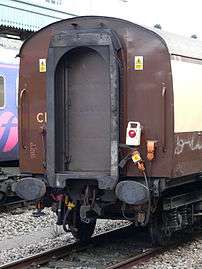
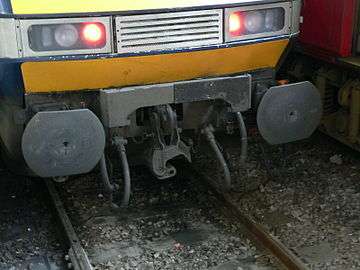
On the formation of British Railways on 1 January 1948, it was decided to produce a new range of standard coaches, instead of perpetuating existing designs, but the new types needed to be compatible with the old. Two of the pre-BR companies (the GWR and the London, Midland and Scottish Railway) favoured the British Standard gangway, whereas the other two (the London and North Eastern Railway and the Southern Railway) used the Pullman type. In the design of their new Mark 1 coaches, British Railways decided to standardise on the Pullman type in view of its resistance to telescoping.[14] These gangways consisted of a flat steel plate, having a large aperture for the passageway. At the bottom it was rivetted to the buffing plate, whilst the top was supported on the coach end by two telescopic spring units. On the coach end was a wooden doorframe; this was connected to the faceplate by a flexible diaphragm made from plasticised asbestos. When two coaches were coupled, a curtain was used to cover the inside surfaces of the diaphragms and faceplates. The doorframe was fitted with a lockable door, of either sliding or hinged type, depending on the interior layout of that end of the coach.[15]
Travelling Post Office

Coaches built for the Travelling Post Office (TPO) services normally had their corridor connections offset to one side. There were two main reasons: there was a perceived security risk should these coaches be coupled to ordinary passenger-carrying coaches, the differing gangway positions minimising the risk of intrusion; and more space was available for sorting tables, the postal workers being able to walk in a straight line between vans without disturbing the sorters. A disadvantage was that when a van was added to a TPO train, it might need to be turned around before it could be used. After the formation of British Railways, most new Mark 1 TPO vans were provided with centre gangways, although a batch which were intended to work with older vans were given offset gangways. These were altered to the standard arrangement in 1973; until then, they had been the only BR Mark 1 gangwayed coaches not to have the Pullman gangway.[16]
Locomotives (corridor tenders)
.jpg)
The London and North Eastern Railway (LNER) decided that from the start of their summer timetable on 1 May 1928, the Flying Scotsman service would run non-stop over the 392.7 miles (632.0 km) between London King's Cross and Edinburgh Waverley. The locomotives to be used were of that railway's class A1,[17] and the schedule was for the journey to be completed in 8 1⁄4 hours.[18] This was too long to allow a single crew to handle without rest; means were therefore sought by which the crew could be changed at approximately the half-way point.[19]

The LNER's locomotive design team, headed by Nigel Gresley, produced a new design of tender which was slightly longer than the old, but built as high and wide as possible without compromising the loading gauge. A passageway was incorporated along the right-hand side, and at the rear end a Pullman type gangway connection was fitted, together with a buckeye coupler, both of which were compatible with LNER coaches; the gangway was of concertina pattern, and was pressed against the corresponding gangway on the leading coach by means of sprung pistons. Although a normal gangway connection was used, the passageway through the tender was only 5 feet (1.52 m) high and 18 inches (0.46 m) wide, and the floor of the passage was 2 feet (0.61 m) above the bottom of the water tank, giving a high step at both ends. The passageway was illuminated by a single circular window in the tender rear panel, placed high up and to the right of the corridor connection.[20] Ten of these tenders were placed in service between April and September 1928, of which three were attached to new locomotives of Class A3; two were attached to existing Class A3 locomotives, and five attached to Class A1 locomotives.[21] The design was patented by Gresley in August 1928.[22]
In service, the relief crew travelled in the front coach of the train, and as the train approached the half-way point, they left their seats and made their way forward through the corridor tender to the locomotive cab. On their arrival, the previous crew then handed over the controls and went back to the seats in the train which had been vacated by the relief crew.[23]
Another corridor tender was built in 1929 for use with the new Class W1 4-6-4 no. 10000;[24] four more were built in 1935 with the first four locomotives of the new Class A4, and a final seven were built with the 1937 batch of Class A4 locomotives, making a total of 22. The original ten were reconditioned in 1936–7 and attached to other Class A4 locomotives. In May 1948, the 1929-built corridor tender was transferred to a locomotive of Class A4, after which all 22 remained with this class until withdrawal.[23][25][26]
In the USA, the Milwaukee Road class A 4-4-2s of 1935 built for the 6½ hour Hiawatha express also used a corridor tender.
Open gangways in urban transit


In the 21st century, a connection between transport units including articulated buses, but usually referring to urban heavy rail rapid transit rolling stock gained popularity. It allows the ability to seamlessly move between cars at any time, without passing through doors and a dangerous open area that is often against the rules. It was also considered to raise the capacity of metro cars by about 10%,[27] a significant improvement for systems such as the New York City Subway where infrastructure and timetables are near or at capacity.
The Toronto Transit Commission (TTC) has used open gangway rolling stock for several years as of 2016, while the Metropolitan Transportation Authority (MTA), the New York City Subway's operator, was considering it for up to 750 railcars of the planned R211 order. Initially they had planned only 10 cars, enough for an experimental prototype train-set, amid fears of crime. However, TTC claims that crime has not been a problem since the implementation of open gangway stock. In July 2016, the state and the MTA announced that along with some major station upgrades, they were increasing the number of open gangway cars to as many as 750, up from 10. [28]
See also
Notes
- ↑ Jenkinson 1978, p. 117.
- ↑ Jenkinson 1988, p. 10.
- ↑ Chant 2002, p. 348.
- ↑ Solomon 2001, p. 101.
- ↑ Harris 1995, p. 9.
- ↑ Harris 1985, p. 38.
- ↑ Harris 1985, p. 23.
- ↑ Harris 1985, p. 40.
- ↑ Harris 1985, pp. 48,51.
- 1 2 3 Harris 1985, p. 24.
- ↑ Harris 1985, p. 75.
- ↑ Harris 1985, p. 77.
- ↑ Essery & Jenkinson 1991, p. 7.
- ↑ Parkin 1991, p. 7,8.
- ↑ Parkin 1991, p. 18,26.
- ↑ Parkin 1991, p. 175.
- ↑ Boddy, Neve & Yeadon 1973, pp. 75–76.
- ↑ Nock 1945, p. 46.
- ↑ Boddy, Neve & Yeadon 1973, p. 68.
- ↑ Boddy, Neve & Yeadon 1973, pp. 68,112.
- ↑ Boddy, Neve & Yeadon 1973, pp. 68–69.
- ↑ Hughes 2001, p. 95.
- 1 2 Boddy et al. 1963, p. 64.
- ↑ Boddy et al. 1984, p. 149.
- ↑ Boddy, Neve & Yeadon 1973, pp. 112–3.
- ↑ Boddy et al. 1984, p. 156.
- ↑ Danielle Furfaro (August 16, 2016). "Here's a glimpse at the future on NYC's subways". New York Post. Retrieved August 16, 2016.
- ↑ "Governor Cuomo Unveils Design of Reimagined MTA Subway Cars and Details Ambitious Plan to Enhance Subway Stations". 2016-07-18. Retrieved 2016-07-19.
References
- Boddy, M.G.; Fry, E.V.; Hennigan, W.; Proud, P.; Yeadon, W.B. (July 1963). Fry, E.V., ed. Part 1: Preliminary Survey. Locomotives of the L.N.E.R. Potters Bar: RCTS.
- Boddy, M.G.; Neve, E.; Yeadon, W.B. (April 1973). Fry, E.V., ed. Part 2A: Tender Engines - Classes A1 to A10. Locomotives of the L.N.E.R. Kenilworth: RCTS. ISBN 0-901115-25-8.
- Boddy, M. G.; Brown, W. A.; Hennigan, W.; Hoole, Ken; Neve, E.; Yeadon, W. B. (September 1984). Fry, E. V., ed. Locomotives of the L.N.E.R., Part 6C: Tender Engines—Classes Q1 to Y10. Kenilworth: RCTS. ISBN 0-901115-55-X.
- Chant, Christopher (2002). The History of North American Rail. Edison, NJ: Chartwell Books. ISBN 0-7858-1455-8.
- Essery, Bob; Jenkinson, David (1991). The Illustrated History of LMS Standard Coaching Stock - I: General Introduction and Non-Passenger Vehicles. Yeovil: Oxford Publishing Co. ISBN 0-86093-450-0. T450.
- Harris, Michael (1985) [1966]. Great Western Coaches from 1890 (3rd ed.). Newton Abbot: David & Charles. ISBN 0-7153-8050-8.
- Harris, Michael (1995). Great Northern Railway and East Coast Joint Stock Carriages from 1905. Headington: Oakwood Press. ISBN 0-85361-477-6. X56.
- Hughes, Geoffrey (2001). Sir Nigel Gresley: The Engineer and his Family. The Oakwood Library of Railway History. Usk: Oakwood Press. ISBN 0-85361-579-9. OL118.
- Jenkinson, David (1978). An Illustrated History of L.N.W.R. Coaches (including West Coast Joint Stock). Headington: Oxford Publishing Co. ISBN 0-902888-90-0.
- Jenkinson, David (1988). British Railway Carriages of the 20th Century - Volume 1: The end of an era, 1901-22. London: Guild Publishing. CN 8130.
- Nock, O.S. (1945). The Locomotives of Sir Nigel Gresley. London: Longmans, Green & Co. 16925.
- Parkin, Keith (1991). British Railways Mark 1 Coaches. Penryn: Pendragon. ISBN 0-906899-49-4.
- Solomon, Brian (2001). The Heritage of North American Steam Railroads. London: Amber Books. ISBN 1-897884-75-3.