Coherer

The coherer is a primitive form of radio signal detector used in the first radio receivers during the wireless telegraphy era at the beginning of the 20th century. Its use in radio was based on the 1890 findings of French physicist Edouard Branly and adapted by other physicists and inventors over the next ten years. The device consists of a tube or capsule containing two electrodes spaced a small distance apart with loose metal filings in the space between. When a radio frequency signal is applied to the device, the metal particles would cling together or "cohere", reducing the initial high resistance of the device, thereby allowing a much greater direct current to flow through it. In a receiver, the current would activate a bell, or a Morse paper tape recorder to make a record of the received signal. The metal filings in the coherer remained conductive after the signal (pulse) ended so that the coherer had to be "decohered" by tapping it with a clapper, such as a doorbell ringer, each time a signal was received, thereby restoring the coherer to its original state. Coherers remained in widespread use until about 1907, when they were replaced by more sensitive electrolytic and crystal detectors.
History
The behavior of particles or metal filings in the presence of electricity or electric sparks was noticed in many experiments well before Edouard Branly's 1890 paper and even before there was proof of the theory of electromagnetism.[1] In 1835 Swedish scientist Peter Samuel Munk[2] noticed a change of resistance in a mixture of metal filings in the presence of spark discharge from a Leyden jar.[3] In 1850 Pierre Guitard found that when dusty air was electrified, the particles would tend to collect in the form of strings. The idea that particles could react to electricity was used in English engineer Samuel Alfred Varley's 1866 lightning bridge, a lightning arrester attached to telegraph lines consisting of a piece of wood with two metal spikes extending into a chamber. The space was filled with powdered carbon that would not allow the low voltage telegraph signals to pass through but it would conduct and ground a high voltage lightning strike.[4] In 1879 the Welsh scientist David Edward Hughes found that loose contacts between a carbon rod and two carbon blocks as well as the metallic granules in a microphone he was developing responded to sparks generated in a nearby apparatus.[3] Temistocle Calzecchi-Onesti in Italy began studying the anomalous change in the resistance of thin metallic films and metal particles at Fermo/Monterubbiano. He found that copper filings between two brass plates would cling together, becoming conductive, when he applied a voltage to them. He also found that other types of metal filings would have the same reaction to electric sparks occurring at a distance, a phenomenon that he thought could be used for detecting lightning strikes.[4] Calzecchi-Onesti's papers were published in il Nuovo Cimento in 1884, 1885 and 1886.
In 1890 French physicist Edouard Branly published On the Changes in Resistance of Bodies under Different Electrical Conditions in a French Journal where he described his thorough investigation of the effect of minute electrical charges on metal and many types of metal filings. In one type of circuit, filings were placed in a tube of glass or ebonite, held between two metal plates. When an electric discharge was produced in the neighbourhood of the circuit, a large deviation was seen on the attached galvanometer needle. He noted the filings in the tube would react to the electric discharge even when the tube was placed in another room 20 yards away. Branly went on to devise many types of these devices based on "imperfect" metal contacts. Branly's filings tube came to light in 1892 in Great Britain when it was described by Dr. Dawson Turner at a meeting of the British Association in Edinburgh.[5][6] The Scottish electrical engineer and astronomer George Forbes suggested that Branly's filings tube might be reacting in the presence of Hertzian waves, a type of air-borne electromagnetic radiation proven to exist by German physicist Heinrich Hertz (later called radio waves).
.jpg)
In 1893 physicist W.B. Croft exhibited Branly's experiments at a meeting of the Physical Society in London. It was unclear to Croft and others whether the filings in the Branly tube were reacting to sparks or the light from the sparks. George Minchin noticed the Branly tube might be reacting to Hertzian waves the same way his solar cell did and wrote the paper "The Action of Electromagnetic Radiation on Films containing Metallic Powders".[5][6] These papers were read by English physicist Oliver Lodge who saw this as a way to build a much improved Hertzian wave detector. On 1 June 1894, a few months after the death of Heinrich Hertz, Oliver Lodge delivered a memorial lecture on Hertz where he demonstrated the properties of "Hertzian waves" (radio), including transmitting them over a short distance, using an improved version of Branly's filings tube, which Lodge had named the "coherer", as a detector. In May 1895, after reading about Lodge's demonstrations, the Russian physicist Alexander Popov built a "Hertzian wave" (radio wave) based lightning detector using a coherer. That same year Italian inventor Guglielmo Marconi demonstrated a wireless telegraphy system using Hertzian waves (radio), based on a coherer.
The coherer was replaced in receivers by the simpler and more sensitive electrolytic and crystal detectors around 1907, and became obsolete.
One minor use of the coherer in modern times was by Japanese tin-plate toy manufacturer Matsudaya Toy Co. who beginning 1957 used a spark-gap transmitter and coherer-based receiver in a range of radio-controlled (RC) toys, called Radicon (abbreviation for Radio-Controlled) toys. Several different types using the same RC system were commercially sold, including a Radicon Boat (very rare), Radicon Oldsmobile Car (rare) and a Radicon Bus (the most popular).[7][8]
Operation

Unlike modern AM radio stations that transmit a continuous radio frequency, whose amplitude (power) is modulated by an audio signal, the first radio transmitters transmitted information by wireless telegraphy (radiotelegraphy), the transmitter was turned on and off (on-off keying) to produce different length pulses of unmodulated carrier wave signal, "dots" and "dashes", that spelled out text messages in Morse code. As a result, early radio receiving apparatus merely had to detect the presence or absence of the radio signal, not convert it to audio. The device that did this was called a detector. The coherer was the most successful of many detector devices that were tried in the early days of radio.
The basis for the operation of the coherer is that metal particles cohere (cling together) and conduct electricity much better after being subjected to radio frequency electricity. The radio signal from the antenna was applied directly across the coherer's electrodes. When the radio signal from a "dot" or "dash" came in, the coherer would become conductive. The coherer's electrodes were also attached to a DC circuit powered by a battery that created a "click" sound in earphones or a telegraph sounder, or a mark on a paper tape, to record the signal. Unfortunately, the reduction in the coherer's electrical resistance persisted after the radio signal was removed. This was a problem because the coherer had to be ready immediately to receive the next "dot" or "dash". Therefore a decoherer mechanism was added, to tap the coherer, mechanically disturbing the particles to reset it to the high resistance state.
Coherence of particles by radio waves is an obscure phenomenon that is not well understood even today. Recent experiments with particle coherers seem to have confirmed the hypothesis that the particles cohere by a micro-weld phenomenon caused by radio frequency electricity flowing across the small contact area between particles.[9][10] The underlying principle of so-called "imperfect contact" coherers is also not well understood, but may involve a kind of tunneling of charge carriers across an imperfect junction between conductors.
Application
.jpg)
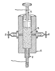
The coherer used in practical receivers was a glass tube, sometimes evacuated, which was about half filled with sharply cut metal filings, often part silver and part nickel. Silver electrodes made contact with the metal particles on both ends. In some coherers the electrodes were slanted so the width of the gap occupied by the filings could be varied by rotating the tube about its long axis, thus adjusting its sensitivity to the prevailing conditions.
In operation, the coherer is included in two separate electrical circuits. One is the antenna-ground circuit shown in the untuned receiver circuit diagram below. The other is the battery-sounder relay circuit including battery B1 and relay R in the diagram. A radio signal from the antenna-ground circuit "turns on" the coherer, enabling current flow in the battery-sounder circuit, activating the sounder, S. The coils, L, act as RF chokes to prevent the RF signal power from leaking away through the relay circuit.
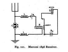
One electrode, A, of the coherer, (C, in the left diagram) is connected to the antenna and the other electrode, B, to ground. A series combination of a battery, B1, and a relay, R, is also attached to the two electrodes. When the signal from a spark gap transmitter is received, the filings tend to cling to each other, reducing the resistance of the coherer. When the coherer conducts better, battery B1 supplies enough current through the coherer to activate relay R, which connects battery B2 to the telegraph sounder S, giving an audible click. In some applications, a pair of headphones replaced the telegraph sounder, being much more sensitive to weak signals, or a Morse recorder which recorded the dots and dashes of the signal on paper tape.

The problem of the filings continuing to cling together and conduct after the removal of the signal was solved by tapping or shaking the coherer after the arrival of each signal, shaking the filings and raising the resistance of the coherer to the original value. This apparatus was called a decoherer. This process was referred to as 'decohering' the device and was subject to much innovation during the life of the popular use of this component. Tesla, for example, invented a coherer in which the tube rotated continually along its axis.
In later practical receivers the decoherer was a clapper similar to an electric bell, operated by an electromagnet powered by the coherer current itself. When the radio wave turned on the coherer, the DC current from the battery flowed through the electromagnet, pulling the arm over to give the coherer a tap. This returned the coherer to the nonconductive state, turning off the electromagnet current, and the arm sprang back. If the radio signal was still present, the coherer would immediately turn on again, pulling the clapper over to give it another tap, which would turn it off again. The result was a constant "trembling" of the clapper during the period that the radio signal was on, during the "dots" and "dashes" of the Morse code signal.
Imperfect junction coherer
There are several variations of what is known as the imperfect junction coherer. The principle of operation (microwelding) suggested above for the filings coherer may be less likely to apply to this type because there is no need for decohering. An iron and mercury variation on this device was used by Marconi for the first transatlantic radio message. An earlier form was invented by Jagdish Chandra Bose in 1899.[11] The device consisted of a small metallic cup containing a pool of mercury covered by a very thin insulating film of oil; above the surface of the oil, a small iron disc is suspended. By means of an adjusting screw the lower edge of the disc is made to touch the oil-covered mercury with a pressure small enough not to puncture the film of oil. Its principle of operation is not well understood. The action of detection occurs when the radio frequency signal somehow breaks down the insulating film of oil, allowing the device to conduct, operating the receiving sounder wired in series. This form of coherer is self-restoring and needs no decohering.
In 1899, Bose announced the development of an "iron-mercury-iron coherer with telephone detector" in a paper presented at the Royal Society, London.[12] He also later received U.S. Patent 755,840, "Detector for electrical disturbances" (1904), for a specific electromagnetic receiver.
Limitations of coherers
Coherers have difficulty discriminating between the impulsive signals of spark-gap transmitters, and other impulsive electrical noise:[13]
This device [the coherer] was publicized as wonderful, and it was wonderfully erratic and bad. It would not work when it should, and it worked overtime when it should not have.— Robert Marriott
All was fish that came to the coherer net, and the recorder wrote down dot and dash combinations quite impartially for legitimate signals, static disturbances, a slipping trolley several blocks away, and even the turning on and off of lights in the building. Translation of the tape frequently required a brilliant imagination
Coherers were also finicky to adjust and not very sensitive. Another problem was that, because of the cumbersome mechanical "decohering" mechanism, the coherer was limited to a receiving speed of 12 - 15 words per minute of Morse code, while telegraph operators could send at rates of 50 WPM, and paper tape machines at 100 WPM.[14][15]
More important for the future, the coherer could not detect AM (radio) transmissions. As a simple switch that registered the presence or absence of radio waves, the coherer could detect the on-off keying of wireless telegraphy transmitters, but it could not demodulate (rectify) the waveforms of AM radiotelephone signals, which began to be experimented with in the first years of the 20th century. This problem was solved by the rectification capability of Reginald Fessenden's hot wire barretter and electrolytic detector. These in turn were replaced by the crystal detector around 1906, and then around 1912 by vacuum tube technologies such as John Ambrose Fleming's thermionic diode and Lee De Forest's Audion (triode) tube.


See also
- Detector (radio)
- Crystal radio
- Spark-gap transmitter
- Radio receiver
- Antique radio
- Camille Papin Tissot
- Wetting current
- Wetting voltage
Further reading
- Phillips, Vivian J. (1980). Early Radio Wave Detectors. London: Inst. of Electrical Engineers. ISBN 0906048249.. A comprehensive description of radio detectors up to the development of the vacuum tube, with many unusual types of coherer.
- Cuff, Thomas Mark (1993). Coherers, a review. Philadelphia, PA, Temple University, Master's Thesis. A technical historical account of the discovery and development of coherers and coherer-like behaviors from the 1800s to 1993, including the investigations, in the 1950s, of using coherers in the, then, new field of digital computers. This thesis examines the similarities among coherers and electrolytic RF detectors, MOM (Metal-Oxide-Metal) 'diodes' used in laser heterodyning, and the STM (Scanning Tunneling Microscope).
References
- ↑ L. W. Turner, Electronics Engineer's Reference Book, Butterworth-Heinemann - 2013, pages 2-3, 2-4
- ↑ Peter Samuel Munk af Rosenschold lecture assistant in Chemistry at the University of Lund was born at Lund in 1804 and died in 1860 (Michael Faraday, Christian Friedirich Schoenbein, The letters of Faraday and Schoenbein 1836-1862: With notes, comments and references to contemporary letters, Williams & Norgate - 1899, page 54)
- 1 2 Eric Falcon and Bernard Castaing, Electrical conductivity in granular media and Branly’s coherer: A simple experiment, page 1
- 1 2 T. K. Sarkar, Robert Mailloux, Arthur A. Oliner, M. Salazar-Palma, Dipak L. Sengupta, History of Wireless, John Wiley & Sons - 2006, pages 261-262
- 1 2 Sungook Hong, Wireless: From Marconi's Black-box to the Audion, page 4
- 1 2 E C Green , The Development of the Coherer And Some Theories of Coherer Action, Scientific American: Supplement, Volume 84 - 1917, page 268
- ↑ Lee, Thomas H. (2004). Planar Microwave Engineering: A Practical Guide to Theory, Measurement, and Circuits. London: Cambridge University Press. p. 11. ISBN 0521835267.
- ↑ Findlay, David A. (September 1, 1957). "Radio Controlled Toys Use Spark Gap" (PDF). Electronics. McGraw-Hill. 30 (9): 190. Retrieved November 11, 2015.
- ↑ E. Falcon, B. Castaing, and M. Creyssels: Nonlinear electrical conductivity in a 1D granular medium, Laboratoire de Physique de l’Ecole Normale Sup'erieure de Lyon UMR 5672 -46 all'ee d’Italie, 69007 Lyon, France
- ↑ Falcona, Eric; Bernard Castaing (April 2005). "Electrical conductivity in granular media and Branly's coherer: A simple experiment" (PDF). American Journal of Physics. USA: American Association of Physics Teachers. 73 (4): 302–306. doi:10.1119/1.1848114. Retrieved 14 November 2013.
- ↑ Bose article by Varun Aggarwal
- ↑ Bondyopadhyay (1988)
- ↑ quoted in Douglas, Alan (April 1981). "The crystal detector". IEEE Spectrum. New York: Inst. of Electrical and Electronic Engineers: 64. Retrieved 2010-03-14. on Stay Tuned website
- ↑ Maver, William Jr. (August 1904). "Wireless Telegraphy To-Day". American Monthly Review of Reviews. New York: The Review of Reviews Co. 30 (2): 192. Retrieved January 2, 2016.
- ↑ Aitken, Hugh G.J. (2014). The Continuous Wave: Technology and American Radio, 1900-1932. Princeton Univ. Press. p. 190. ISBN 1400854601.
External links
| Wikimedia Commons has media related to Coherers. |
- Web archive backup: "The Coherer". World of Wireless, Virtual radiomuseum.
- "Coherer / Receiver". Marconi Calling Company.
- Slaby, Adolphus, "The New Telegraphy, Recent experiments in telegraphy with sparks.". The Century Magazine. April, 1898. (Earlyradiohistory.us)
- Hirakawa Institute of Technology(Japan),"Coherer".
- "Tesla's US Patent: 613,809". ShareAPic.net.
- Coherer: history & operation