Optical chopper
An optical chopper is a device which periodically interrupts a light beam. Three types are available: variable frequency rotating disc choppers, fixed frequency tuning fork choppers, and optical shutters. A rotating disc chopper was famously used in 1849 by Hippolyte Fizeau in the first non-astronomical measurement of the speed of light.
Use in science laboratories
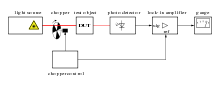
Optical choppers, usually rotating disc mechanical shutters, are widely used in science labs in combination with lock-in amplifiers.[1] The chopper is used to modulate the intensity of a light beam, and a lock-in amplifier is used to improve the signal-to-noise ratio.
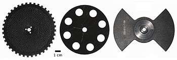
To be effective, an optical chopper should have a stable rotating speed. In cases where the 1/f noise is the main problem, one would like to select the maximum chopping frequency possible. This is limited by the motor speed and the number of slots in the rotating disc, which is in turn limited by the disc radius and the beam diameter.
Examples
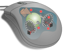
Optical incremental rotary encoders are a form of choppers. These are used in many industrial machines. Some early anti-lock braking systems used rotary encoders for wheel speed sensors. Late 20th century opto-mechanical computer mice used two encoders for X-Y position measurement. Optical linear encoders also exist.
LCD televisions use millions of LCD shutters paired with red, green or blue filters to control the color of the pixels on the screen.
Movie cameras use an optical shutter to record individual frames of the movie. Movie projectors use an optical shutter synchronized with the movie frames to produce the effect of apparent motion on the movie screen.
Liquid crystal shutter glasses are used in conjunction with a synchronized display screen to create the illusion of a three-dimensional image.
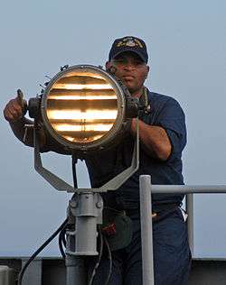
Light signals are sent at sea and at airports using a signal lamp with a hand operated shutter.
| Examples of optical choppers in use | ||||
|---|---|---|---|---|
|
See also
References
- ↑ Wolfson R. (1991). "The lock-in amplifier: A student experiment" (PDF). Am J Phys. 59 (6). pp. 569–572. doi:10.1119/1.16824.
External links
Frequently asked questions on optical choppers.