Choke (electronics)

In electronics, a choke is an inductor used to block higher-frequency alternating current (AC) in an electrical circuit, while passing lower-frequency or direct current (DC). A choke usually consists of a coil of insulated wire often wound on a magnetic core, although some consist of a donut-shaped "bead" of ferrite material strung on a wire. The choke's impedance increases with frequency. Its low electrical resistance passes both AC and DC with little power loss, but it can limit the amount of AC due to its reactance.
The name comes from blocking—"choking"—high frequencies while passing low frequencies. It is a functional name; the name "choke" is used if an inductor is used for blocking or decoupling higher frequencies, but is simply called an "inductor" if used in electronic filters or tuned circuits. Inductors designed for use as chokes are usually distinguished by not having the low-loss construction (high Q factor) required in inductors used in tuned circuits and filtering applications.
Types and construction
Chokes are divided into two broad classes:
- Audio frequency chokes (AFC) – designed to block audio and power line frequencies while allowing DC to pass
- Radio frequency chokes (RFC) – designed to block radio frequencies while allowing audio and DC to pass.
Audio frequency chokes
Audio frequency chokes (AFC) usually have ferromagnetic cores to increase their inductance. They are often constructed similarly to transformers, with laminated iron cores and an air gap. A major use in the past was in power rectifiers and direct current motor controllers to produce direct current (DC), where they were used in conjunction with large electrolytic capacitors to remove the voltage ripple(AC) at the output DC. A rectifier circuit designed for a choke-output filter may produce too much DC output voltage and subject the rectifier and filter capacitors to excessive in-rush and ripple currents if the inductor is removed. However, modern electrolytic capacitors with high ripple current ratings, and voltage regulators that remove more power supply ripple than chokes could, have eliminated heavy, bulky chokes from mains frequency power supplies. Smaller chokes are used in switching power supplies to remove the higher-frequency switching transients from the output and sometimes from feeding back into the mains input. They often have toroidal ferrite cores.
Radio frequency chokes
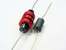
Radio frequency chokes (RFC) often have iron powder or ferrite cores. They are often wound in complex patterns (basket winding) to reduce self-capacitance and proximity effect losses. Chokes for even higher frequencies have non-magnetic cores and low inductance.
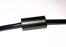
A modern form of choke used for eliminating digital RF noise from lines is the ferrite bead, a cylindrical or torus-shaped core of ferrite slipped over a wire. These are often seen on computer cables. A typical RF choke value could be 2 millihenries.
Common-mode chokes

Common-mode chokes, where two coils are wound on a single core, are useful for prevention of electromagnetic interference (EMI) and radio frequency interference (RFI) from power supply lines and for prevention of malfunctioning of electronic equipment. They pass differential currents (equal but opposite), while blocking common-mode currents.[2] Magnetic fields produced by differential-mode currents in the windings tend to cancel each other out. Thus, the choke presents little inductance or impedance to differential-mode currents. This also means the core will not saturate even for large differential-mode currents and the maximum current rating is instead determined by the heating effect of the winding resistance. Common-mode currents, however, see a high impedance due to the combined inductance of the windings.
References
- ↑ "Understanding Common Mode Noise". Pulse. Retrieved 17 April 2012.
- ↑ http://www.murata.com/products/emc/knowhow/pdf/26to30.pdf
Further reading
- Wildi, Théodore (1981) Electrical power technology, ISBN 978-0471077640