Chirped pulse amplification

Chirped pulse amplification (CPA) is a technique for amplifying an ultrashort laser pulse up to the petawatt level with the laser pulse being stretched out temporally and spectrally prior to amplification.[1] CPA is the current state of the art technique which all of the highest power lasers (greater than about 100 terawatts, with the exception of the ~500 TW National Ignition Facility) in the world currently utilize. Some examples of these lasers are the Vulcan Petawatt Upgrade at the Rutherford Appleton Laboratory's central laser facility, the Diocles Laser at the University of Nebraska-Lincoln, the Gekko Petawatt laser at the Gekko XII facility in the Institute of Laser Engineering at Osaka University, the OMEGA EP laser at the University of Rochester's Lab for Laser Energetics and the now dismantled petawatt line on the former Nova laser at the Lawrence Livermore National Laboratory. Apart from these state-of-the-art research systems, a number of commercial manufacturers sell Ti:sapphire-based CPAs with peak powers of 10 to 100 gigawatts.
Chirped-pulse amplification was originally introduced as a technique to increase the available power in radar in 1960.[2] CPA for lasers was invented by Gérard Mourou and Donna Strickland at the University of Rochester in the mid 1980s.[3] Before then, the peak power of laser pulses was limited because a laser pulse at intensities of gigawatts per square centimeter causes serious damage to the gain medium through nonlinear processes such as self-focusing. For example, some of the most powerful compressed CPA laser beams, even in an unfocused large aperture (after exiting the compression grating) can exceed intensities of 700 gigawatts/cm2, which if allowed to propagate in air or the laser gain medium would instantly self focus and form a plasma or cause filament propagation, both of which would ruin the original beam's desirable qualities and could even cause back-reflection potentially damaging the laser's components. In order to keep the intensity of laser pulses below the threshold of the nonlinear effects, the laser systems had to be large and expensive, and the peak power of laser pulses was limited to the high gigawatt level or terawatt level for very large multi beam facilities.
In CPA, on the other hand, an ultrashort laser pulse is stretched out in time prior to introducing it to the gain medium using a pair of gratings that are arranged so that the low-frequency component of the laser pulse travels a shorter path than the high-frequency component does. After going through the grating pair, the laser pulse becomes positively chirped, that is, the high-frequency component lags behind the low-frequency component, and has longer pulse duration than the original by a factor of 103 to 105. Then the stretched pulse, whose intensity is sufficiently low compared with the intensity limit of gigawatts per square centimeter, is safely introduced to the gain medium and amplified by a factor 106 or more. Finally, the amplified laser pulse is recompressed back to the original pulse width through the reversal process of stretching, achieving orders of magnitude higher peak power than laser systems could generate before the invention of CPA.
In addition to the higher peak power, CPA makes it possible to miniaturize laser systems (the compressor being the biggest part). A compact high-power laser, known as a tabletop terawatt laser (T3 laser), can be created based on the CPA technique.
Stretcher and compressor design
There are several ways to construct compressors and stretchers. However, a typical Ti:sapphire-based chirped-pulse amplifier requires that the pulses are stretched to several hundred picoseconds, which means that the different wavelength components must experience about 10 cm difference in path length. The most practical way to achieve this is with grating-based stretchers and compressors. Stretchers and compressors are characterized by their dispersion. With negative dispersion, light with higher frequencies (shorter wavelengths) takes less time to travel through the device than light with lower frequencies (longer wavelengths). With positive dispersion, it is the other way around. In a CPA, the dispersions of the stretcher and compressor should cancel out. Because of practical considerations, the stretcher is usually designed with positive dispersion and the compressor with negative dispersion.
In principle, the dispersion of an optical device is a function , where is the time delay experienced by a frequency component . (Sometimes the phase is used, where c is the speed of light and is the wavelength.) Each component in the whole chain from the seed laser to the output of the compressor contributes to the dispersion. It turns out to be hard to tune the dispersions of the stretcher and compressor such that the resulting pulses are shorter than about 100 femtoseconds. For this, additional dispersive elements may be needed.


With gratings

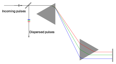
Figure 1 shows the simplest grating configuration, where long-wavelength components travel a larger distance than the short-wavelength components (negative dispersion). Often, only a single grating is used, with extra mirrors such that the beam hits the grating four times rather than two times as shown in the picture. This setup is normally used as a compressor, since it does not involve components that could lead to unwanted side-effects when dealing with high-intensity pulses. The dispersion can be tuned easily by changing the distance between the two gratings.


Figure 2 shows a more complicated grating configuration that involves focusing elements, here depicted as lenses. The lenses are placed at a distance from each other (they act as a 1:1 telescope), and at a distance from the gratings. If , the setup acts as a positive-dispersion stretcher and if , it is a negative-dispersion stretcher. And the case is used in the pulse shaper. Usually, the focusing element is a spherical or cylindrical mirror rather than a lens. As with the configuration in Figure 1, it is possible to use an additional mirror and use a single grating rather than two separate ones. This setup requires that the beam diameter is very small compared to the length of the telescope; otherwise undesirable aberrations will be introduced. For this reason, it is normally used as a stretcher before the amplification stage, since the low-intensity seed pulses can be collimated to a beam with a small diameter.


With prisms
It is possible to use prisms rather than gratings as a dispersive elements, as in Figure 3. Despite such a simple change the set-up behaves quite differently, as to first order no group delay dispersion is introduced. Such a stretcher/compressor can have both a positive or negative dispersion, depending on the geometry and the material properties of the prisms. With lenses, the sign of the dispersion can be reversed, similar to Figure 2. For a given distance between the dispersive elements, prisms generate much less dispersion than gratings. Prisms and gratings are sometimes combined to correct higher order dispersion ("grisms"), in which case the distance between the prisms is on the order of 10 meters rather than 50 cm as with a grating compressor. Gratings lose power into the other orders while prisms lose power due to Rayleigh scattering.
Other techniques
Some other techniques can be used for stretching and compressing pulses, but these are not suitable as the main stretcher/compressor in CPA due to their limited amount of dispersion and due to their inability to handle high-intensity pulses.
- A pulse can be stretched simply by letting it propagate through a thick slab of transparent material, such as 200 mm glass. As with the prisms, only a limited amount of dispersion can be achieved within physically practical dimensions. Outside the visible-light spectrum, materials exist both for positive and negative dispersion. For visible and near-infrared wavelengths, almost all transparent materials have positive dispersion. However, glass fibres can have their dispersion tailored to meet the needs.
- One or multiple reflections between a pair of chirped mirrors or similar device allow any form of chirp. This is often used in conjunction with the other techniques to correct for higher orders.
- The Dazzler is a commercial pulse shaper in which light is diffracted from an acoustic wave. By tuning the timing, frequency, and amplitude of the acoustic wave, it is possible to introduce arbitrary dispersion functions with a maximum delay of a few picoseconds.
- A phase-shifting mask can be placed in the focal plane of the stretcher in Fig. 2, which introduces additional dispersion. Such a mask can be an LCD array, where the phase shift can be tuned by changing the voltage on the pixels. This can generate arbitrary dispersion functions with a maximum of a few tens of picoseconds of delay. Such a setup is called a pulse shaper.
See also
References
- ↑ Encyclopedia of Laser Physics and Technology: https://www.rp-photonics.com/chirped_pulse_amplification.html
- ↑ G. E. Cook,"Pulse Compression-Key to More Efficient Radar Transmission", IEEE Proc. IRE 48, 310 (1960)
- ↑ D. Strickland and G. Mourou, “Compression of amplified chirped optical pulses”, Opt. Commun. 56, 219 (1985)