Chain boat

A chain boat,[1][2] chain tug[3] or chain-ship[4] was a type of river craft, used in the second half of the 19th century and first half of the 20th century on many European rivers, that made use of a steel chain laid along the riverbed for its propulsion.[2][5][6] The chain was hauled by a steam engine mounted on board and enabled the boat to tow a string of barges.[2][5][7][8] In Germany, such a boat was variously referred to as a Kettenschleppschiff, Kettenschlepper, Kettendampfer or Kettenschiff and in France as a toueur.[5][9]
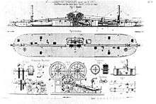
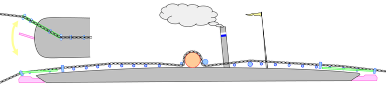
The chain was raised out of the water over a boom at the bow of the ship and led over the deck along the ship's axis to the chain engine amidships. The transfer of power from the steam engine to the chain was usually achieved using a drum winch. From there the chain was led over the deck to another boom at the stern and lowered once more into the river. By moving the stern boom and the two rudders, front and aft, from side to side it was possible to replace the chain in the centre of the river again, even when negotiating river bends.[6]
History
Chain boat navigation revolutionised inland shipping during the Industrial Revolution in the second half of the 19th century in Europe and superseded the hitherto commonplace haulage of barges by draught animals or people. The chain drive of these riverboats made optimal use of still relatively low-powered steam engines of that period. In addition, the boats were especially well suited to the difficult condition of river navigation that pertained at that time: many rivers were shallow or fast-flowing and effectively precluded the use of paddle steamers. As a result, chain boats were soon being used on many rivers across Europe. But by the first half of the 20th century they were increasingly threatened by competition from ever more powerful paddle steamers, something that was aided by the canalization of rivers.[10]
The first designs and early technical stages in the development of chain boats took place in the mid-19th century, especially in France. The prototype of all later chain boats on the rivers Elbe, Neckar and Main was the French steamboat La Ville de Sens, which was built by the German engineer, M Dietz, around 1850 in Bordeaux and plied the upper Seine between Paris and Montereau. Its technically very advanced operating principle and its engineering features were adopted by all the later European chain steamers.[6]
Design
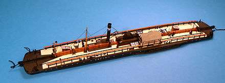
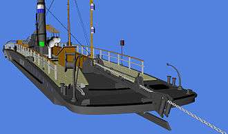
The hull of these symmetrically-designed boats was almost level with the surface of the water at the bow and stern. This design reduced the power needed to lift the tow chain onto the bow of the boat and also reduced the draught at the bow.[11] The greater height of the boat in the centre made it easier to accommodate the steam engine. This deck shape - low at the bow and stern, and higher in the centre - is typical of all subsequently built chain boats.
Chain boats were favoured on shallow rivers with fast currents. This was the reason for the flat, shallow draught of their keels. Chain boats optimized for particularly shallow water had a draught of only 40 to 50 centimetres (16 to 20 in) when unladen. Even fully laden with coal, their draught was only about 70 to 75 centimetres (28 to 30 in).[12] This shallow draught enabled river transportation even in the dry summer months when the water level of rivers could be very low.
Shorter chain boats - with lengths from 30 to 40 metres (100 to 130 ft), and widths from 5 to 6 metres (15 to 20 ft) - were more manoeuvrable and well suited to narrow rivers with many bends, for example on the Saale. Longer craft - with lengths from 45 to 55 metres (150 to 180 ft), and widths from 7 to 10 metres (25 to 35 ft) - were more suited to relatively deep rivers such as the Elbe. The deeper a waterway was, the greater the power needed to lift the heavy chain. The bow of the ship was pulled down further. On larger boats this effect is less.[13]
The hull itself was made of iron or wood and could withstand light impacts with the riverbed. If, however, it was holed the hull was compartmentalized internally by several waterproof bulkheads that prevented the craft from sinking. Below deck were the steam engine, the coal bunkers and the crew accommodation.[6]
Control and navigation
In chain boat navigation the chain was simply laid "loose" on the riverbed for long distances of up to several hundred kilometres. Only the deadweight of the massive chain, which weighed about 15 kilograms per metre (30 lb/yd) or 15 tonnes per kilometre (27 ton/mi), and its natural snagging on the sand and stones of the riverbed provided resistance, so that the chain boat and its attached barges could haul themselves along the chain. The water bore the weight of the boats and barges, whilst the chain only had to cope with the power of the engine. The chain was only anchored at its two ends so that boats could continue to haul themselves to the end of the chain route.[13]
A problem was caused by sideways displacement of the chain. At bends in the river there was a tendency for the chain, that was laid in a curve, to increasingly pull itself straight and so move towards the inside of the bend. In order to prevent this, chain boats were fitted, fore and aft, with large, powerful rudders.[13] These rudders sometimes had a length of over four metres and were worked with the aid of control wheels on the deck.
At the bow and stern of the boat the chain was led along a boom that projected well beyond the end of the deck. This prevented the chain from hitting the long rudders. The booms were movable and could be swung sideways using a hand crank. The boat could thereby be oriented at an angle to the direction of the chain. This also improved the chances of replacing the chain back in the centre of the river.[13]
The boom was also fitted with chain interception equipment so that, in the event of the chain breaking, it would not be able to run away. If the chain catch was not quick enough to hook into the chain, it would simply run away and disappear into the river. It then had to be painstakingly located with a drag anchor and salvaged.[14]
Chain driver
In the first generation of chain boats the chain ran over chain drums at the side of the boat. In fast-flowing currents or when there were problems lifting the chain due to silting or obstacles on the riverbed such as large rocks, the boat could swing off-course markedly and list to one side. As a result, on later chain boats, the chain drive was always located in the middle of the boat.[13]
Drum winch

The older chain boats on the Elbe, the chain steamers on the Neckar and the three craft on the Main belonging to the Hessian Mainkette company used a drum winch to transfer power. In order to ensure the necessary traction on the chain on the driving drums, the chain was wound several times around two traction drums placed one behind the other in the centre of the boat. The chain ran in four to five grooves and was alternately wound over the front and rear drums.[15]
The disadvantage of this method was that the chain frequently broke. This did not simply occur due to the overloading of the chain by the length of the barge train. It has been calculated that even if the chain links wore down to half their original cross-section, this force would not have led to a break.[16] Rather the problem lay in the fact that frictional wear on the forward traction drum was much heavier than on the rear. And once the diameters of the two drums became unequal, more chain wrapped around the after drum than could be handled by the forward one. This could produce tensions both on the drums and between them that were so large that the chain links could not withstand the tensile load and their fracture limit was exceeded.[17]
This effect became even more pronounced if the chain became twisted, e.g., the chain was pulled to one side or had even formed knots. This increased the turn radius by up to 25%, whereby the 5% elastic limit of the chain was reached.
The transfer of tractive force from the drums to the chain was only achieved by friction. If frost or ice built up, the chain could slip. In such events, hot water was poured over the drums.[14]
Another problem with drum winches was the relatively large length of chain - 30 to 40 metres (100 to 130 ft) - that had to be wound several times around the two drums. If the chain boat was only used to haul barges upstream, it could not simply reduce the amount of chain needed for the drums on the way back otherwise, after a certain time, the surplus chain would pile up at the head of the operating section and there would be no slack at the start. In order to try and avoid this problem, the chain boat always carried the corresponding section of chain with it downstream and dropped it at the start of the chain route.[18] As a result, there was a continual movement of the chain, that made control more difficult in more dangerous sections of the river, such as rapids. In particular, reinforced chain sections that were deliberately used, moved continually upstream. Also jettisoning the chain temporarily when two chain boats met was relatively difficult due to the multiple windings of the chain round the two drums.[19]
Many of the chain steamers without their own auxiliary engines had different gearing for moving upstream and downstream. When travelling upstream, it was designed for higher traction; when travelling downstream it was engineered for faster speed.[20]
Chain grip-wheel

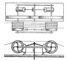
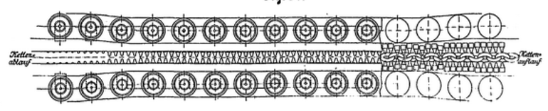
The chain grip-wheel[10] (Kettengreifrad) was designed in May 1892 by Ewald Bellingrath, the director general of the German Elbe shipping company, Kette, in Übigau, in order to overcome the problem of continual chain breakages. This device was used in various chain ships on the Elbe as well as the eight chain boats of the Royal Bavarian Chain Boat Company on the River Main. The idea of the mechanism was to use just one drum or wheel for the actual drive and not to wrap the chain around it several times, but to wind it only partially over the wheel (Diagram 1). The design was supposed to engage the chain securely without letting it slip. It was also supposed to work with different chain thicknesses and lengths of chain link, and independently of their orientation (e.g. angled or on their side). Even if a knot formed in the chain the design was supposed to respond without a problem.[16]
The chain was engaged in the transmission area by many movable side pins that hooked the chain from the left and right hand sides (Diagram 2). Critics were initially concerned that the many individual moving components of the "catcher" would quickly wear. This fear was allayed, however, by a three-year-long trial that began in May 1892. On the contrary, by using a catcher, the transmission of power was improved so that more barges could be hauled in one string. As a consequence all new chain boats built by Kette in Übigau were fitted with catchers.[16]
On the River Main, however, the chain grip-wheels were replaced by drum winches again in 1924, because the first ones were too prone to failure.[14]
Electromagnetic drum
Another attempt to reduce the frequency of chain breakages and the movement of the chain in the river came from France and was introduced in November 1892 on the Lower Seine near Paris.[18] Its inventor, de Bovet, developed a technique to increase the friction on the transmission drum by magnetic force. Here, too, the chain was only wound three-quarters of the way around the traction drum. The engagement of the chain on the traction drum was achieved by magnetic force created by electromagnets that were built into it. The electric current needed for this was generated by its own engine and a ca. 3 HP dynamo.[17]
The magnetic force was sufficient, despite the short length for which the chain was wrapped around the drum, on a trial with an old, 9 kg/m (18 lb/yd) chain to generate a tractive force of around 6,000 kilograms-force (13,000 lbf).[17]
Auxiliary engines
In addition to the main engine for hauling the chain, most of the later chain boats had an auxiliary engine. This enabled boats to be driven without needing to use the chain, and was mainly used when travelling downstream.[21] Downstream journey times were thus reduced because of the higher boat speeds that could be attained and because it was no longer necessary to follow the time-consuming and complicated passing procedure when boats travelling in opposite directions on the same chain encountered one another. In addition, it spared wear and tear on the chain.
Water turbines
.svg.png)
.svg.png)
.JPG)
In 1892 chain boats using Zeuner water turbines were introduced on the Elbe. They were a precursor of the present-day hydrojet propulsion systems. In addition to faster downstream travel times, the auxiliary engine also enabled steering corrections during chain operations and simplified turning manoeuvres. Water turbines were used on several chain boats on the Elbe and on the Bavarian chain boats on the Main.[20]
Water was sucked in through two rectangular intakes in the side of the chain steamer's hull. It then flowed through the turbine inside the hull. The turbine accelerated the water and forced it through the rear-facing outlets in the side of the hull. The outflowing jets of water propelled the boat forwards (upper diagram of the elevation view). To reverse the direction of travel, the reversing element was swung around so that water was forced in the opposite direction (lower diagram of the elevation view). The pump direction of the turbine was always the same, regardless.[22][23]
These second generation chain steamers were equipped with two of these water turbines, which were found on the port and starboard sides.[24] During a turning manoeuvre the water flowed forwards on one side and backwards on the other in order to rotate the boat.[22]
Paddle wheels and screw propellers
On the Danube, chain ships were unable to travel downstream on the chain because of strong currents. If the chain boat was forced to stop suddenly, for example as a result of a chain breakage, there was a real danger that the barges at the rear would run into those at the front, causing a shipping accident.[25] They therefore had large, side-mounted paddle wheels as auxiliary propulsion for the downstream journey which were driven by engines with a rating of 300–400 hp.
The third type of auxiliary propulsion was the screw propeller.[26] This type of auxiliary system was used by some craft on the Danube for downstream journeys in order to enable barges to be towed in that direction as well.[25]
References
- ↑ National Geographic Society (1937). The National Geographic Magazine, Jan-Jun 1937, pp. xxi and 552.
- 1 2 3 John MacGregor (1867). The voyage alone in the yawl "Rob Roy": from London to Paris, and back etc., London: Maranda merrill, Son and Marston, pp. 97-99.
- ↑ McKnight, Hugh (1985). Cruising French Canals and Rivers. Seven Seas Press. p. 126. ISBN 9780915160822.
- ↑ Roger Pilkington (1969). Small boat to Northern Germany, Macmillan, pp. 90, 91 and 95.
- 1 2 3 Kettenschifffahrt definition in Schifffahrts-Lexikon, by J. Friedrichson, p. 149. Retrieved 1 Mar 2014.
- 1 2 3 4 Willi Zimmermann: Über Seil und Kettenschiffahrt, Beiträge zur Rheinkunde 1979, Rheinmuseum Koblenz (digitalized version by Peter Haas; pdf; 5.9 MB)
- ↑ MacGregor (1867), p. 97-98 states "The power of this chain-boat is so great that it will pull along, and that too against the rapid stream, a whole string of barges, several of them of 300 tons' burthen, while the long fleet advances steadily though slowly, and the irresistible engine works with smokeless funnels, but with groanings within, telling of tight-strained iron, and loud undertoned breaths of confined steam."
- ↑ Hearst's International, Volume 3 (1902) by International Magazine Company. Retrieved 12 Mar 2014.
- ↑ Roger Pilkington (1965). Small boat in Southern France, Melbourne, Toronto, p. 33.
- 1 2 K. Dietze: Chain and Rope Towage on German Rivers. In: International marine engineering, Volume 16, New York 1911, pp. 433–439
- ↑ Eduard Weiß: "Die Kettenschlepper der kgl. bayerischen Kettenschleppschiffahrt auf dem oberen Main" in der Zeitschrift des Vereins Deutscher Ingenieure, Vol. 45, 1901, No. 17, pp. 578–584
- ↑ Theodor Grötschel und Helmut Düntzsch: Betriebsmittelverzeichnis der KETTE – Deutsche Elbschiffahrts-Gesellschaft
- 1 2 3 4 5 Zeitschrift für Bauwesen Volume 16, Berlin 1864, p. 300, Verein für Eisenbahnkunde zu Berlin, Protokoll vom 10. November 1863 (digitalized version)
- 1 2 3 Otto Berninger: "Die Kettenschiffahrt auf dem Main" in the Main Shipping Reports of the Society for the Promotion of the Wörth am Main Shipping and Shipbuilding Museum, News Sheet No. 6, April 1987, 111 pages.
- ↑ Architektenverein zu Berlin: Deutsche Bauzeitung, Volume 2, Verlag Carl Beelitz, 1868, S. 100, (Google Books), (description of the 1st German chain boat between Neustadt and Buckau)
- 1 2 3 C. Busley (1895) (in German), Bestrebungen und Erfolge im Schiffbau, Volume XXXIX, Zeitschrift des Verlags deutscher Ingenieure, pp. 704/705
- 1 2 3 Otto Lueger. "Lexikon der gesamten Technik". Retrieved 11 November 2009. – 2. Auflage 1904–1920
- 1 2 A. Schromm: Kettenschifffahrt und Elektricität. In: Zeitschrift für Elektrotechnik, Jahrgang 13, Vienna, 1895, pp. 264–266, online Internet Archive
- ↑ Das Ziehen und Fortbewegen der Schiffe auf Canälen, canalisierten Flüssen und freifließenden Strömen, Binnenschiffahrts-Congress im Haag im Jahre 1894, In: Alfred Weber Ritter von Ebenhof: Bau Betrieb und Verwaltung der natürlichen und künstlichen Wasserstrassen auf den internationalen Binnenschifffahrts-Congressen in den Jahren 1885 bis 1894, Verlag des K.K. Ministeriums des Inneren, Vienna, 1895, pp. 312–327
- 1 2 Sigbert Zesewitz, Helmut Düntzsch, Theodor Grötschel: Kettenschiffahrt. VEB Verlag Technik, Berlin, 1987, ISBN 3-341-00282-0
- ↑ Otto Berninger Die Kettenschleppschifffahrt auf dem Main at www.main-netz.de. Retrieved 4 Mar 2014.
- 1 2 K. Dietze: Chain and Rope Towage on German Rivers. In: International marine engineering, Volume 16, New York 1911, pp. 498–502
- ↑ Schiffsantrieb mittels der Marchand'schen Doppelturbine. at dingler.culture.hu-berlin.de. Retrieved 4 Mar 2014.
- ↑ Kettenschleppdampfer "Gustav Zeuner" at www.kettendampfer-magdeburg.de. Retrieved 4 Mar 2014.
- 1 2 Georg Schanz: "Studien über die bay. Wasserstraßen Band 1, Die Kettenschleppschiffahrt auf dem Main", C.C. Buchner Verlag, Bamberg, 1893, pp. 1–7 – (digitalized version) by Digitalis, Library for Economic and Social History, Cologne, retrieved 29 October 2009
- ↑ Carl Victor Suppán: Wasserstrassen und Binnenschiffahrt. A. Troschel: Berlin-Grunewald 1902 Vor- und Nachtheile der Tauerei. pp. 266–269 FB on the Internet Archive
Literature
- Sigbert Zesewitz, Helmut Düntzsch, Theodor Grötschel: Kettenschiffahrt. VEB Verlag Technik, Berlin, 1987, ISBN 3-341-00282-0
- Kettenschleppschiffahrt. In: Otto Lueger: Lexikon der gesamten Technik und ihrer Hilfswissenschaften, Vol. 5, 2nd completed revised edition, Deutsche Verlagsanstalt: Stuttgart und Leipzig, 1907, pp. 460–462 zeno.org
- Georg Schanz: "Studien über die bay. Wasserstraßen Band 1, Die Kettenschleppschiffahrt auf dem Main", C.C. Buchner Verlag, Bamberg, 1893 (digitalised text from the Library of the Seminar for Economic and Social History of the University of Cologne)
- Theodor Grötschel und Helmut Düntzsch: Betriebsmittelverzeichnis der KETTE – Deutsche Elbschiffahrts-Gesellschaft. In: Ewald Bellingrath: Ein Leben für die Schiffahrt, Schriften des Vereins zur Förderung des Lauenburger Elbschiffahrtsmuseums e.V., Vol. 4, Lauenburg, 2003
- Carl Victor Suppán: Wasserstrassen und Binnenschiffahrt. A. Troschel: Berlin-Grunewald, 1902, Section: Dampfschiffahrt. (Ketten- und Seiltauer. pp. 261/262, Tauereibetrieb. pp. 262–265, Auf- und Abnehmen der Kette. p. 265, Kettenrolle mit Fingerlingen. p. 266, Elektrische Kettenrolle. p. 266, Vor- und Nachtheile der Tauerei. pp. 266–269, Versuche mittels endloser Kette. pp. 269/270)
External links
| Wikimedia Commons has media related to Chain ships. |
| Wikisource has original text related to this article: |
- Video of a journey on an electric chain boat through the Tunnel of Riqueval, retrieved 15 November 2010
- Forum with many old photographs of chain boats from France (French), retrieved 12 July 2013
Modern merchant ships | ||
|---|---|---|
| Dry cargo | ||
| Tankers | ||
| Passenger | ||
| Support | ||
| Other | ||