Ceramic matrix composite
Ceramic matrix composites (CMCs) are a subgroup of composite materials as well as a subgroup of technical ceramics. They consist of ceramic fibres embedded in a ceramic matrix, thus forming a ceramic fibre reinforced ceramic (CFRC) material. The matrix and fibres can consist of any ceramic material, whereby carbon and carbon fibres can also be considered a ceramic material.
Introduction
The motivation to develop CMCs was to overcome the problems associated with the conventional technical ceramics like alumina, silicon carbide, aluminium nitride, silicon nitride or zirconia – they fracture easily under mechanical or thermo-mechanical loads because of cracks initiated by small defects or scratches. The crack resistance is – like in glass – very low. To increase the crack resistance or fracture toughness, particles (so-called monocrystalline whiskers or platelets) were embedded into the matrix. However, the improvement was limited, and the products have found application only in some ceramic cutting tools. So far only the integration of long multi-strand fibres has drastically increased the crack resistance, elongation and thermal shock resistance, and resulted in several new applications.
Carbon (C), special silicon carbide (SiC), alumina (Al2O3) and mullite (Al2O3–SiO2) fibres are most commonly used for CMCs. The matrix materials are usually the same, that is C, SiC, alumina and mullite.
Generally, CMC names include a combination of type of fibre/type of matrix. For example, C/C stands for carbon-fibre-reinforced carbon (carbon/carbon), or C/SiC for carbon-fibre-reinforced silicon carbide. Sometimes the manufacturing process is included, and a C/SiC composite manufactured with the liquid polymer infiltration (LPI) process (see below) is abbreviated as LPI-C/SiC.
The important commercially available CMCs are C/C, C/SiC, SiC/SiC and Al2O3/Al2O3. They differ from conventional ceramics in the following properties, presented in more detail below:
- Elongation to rupture up to 1%
- Strongly increased fracture toughness
- Extreme thermal shock resistance
- Improved dynamical load capability
- Anisotropic properties following the orientation of fibers
Manufacture
The manufacturing processes usually consist of the following three steps:
- Lay-up and fixation of the fibres, shaped as the desired component
- Infiltration of the matrix material
- Final machining and, if required, further treatments like coating or impregnation of the intrinsic porosity.
The first and the last step are almost the same for all CMCs: In step one, the fibres, often named rovings, are arranged and fixed using techniques used in fibre-reinforced plastic materials, such as lay-up of fabrics, filament winding, braiding and knotting. The result of this procedure is called fibre-preform or simply preform.
For the second step, five different procedures are used to fill the ceramic matrix in between the fibres of the preform:
- Deposition out of a gas mixture
- Pyrolysis of a pre-ceramic polymer
- Chemical reaction of elements
- Sintering at a relatively low temperature in the range 1000–1200 °C
- Electrophoretic deposition of a ceramic powder
Procedures one, two and three find applications with non-oxide CMCs, whereas the fourth one is used for oxide CMCs; combinations of these procedures are also practised. The fifth procedure is not yet established in industrial processes. All procedures have sub-variations, which differ in technical details. All procedures yield a porous material.
The third and final step of machining – grinding, drilling, lapping or milling – has to be done with diamond tools. CMCs can also be processed with a water jet, laser, or ultrasonic machining.
Ceramic fibres
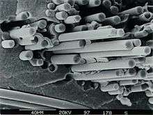
Ceramic fibres in CMCs can have a polycrystalline structure, as in conventional ceramics. They can also be amorphous or have inhomogeneous chemical composition, which develops upon pyrolysis of organic precursors. The high process temperatures required for making CMCs preclude the use of organic, metallic or glass fibres. Only fibres stable at temperatures above 1000 °C can be used, such as fibres of alumina, mullite, SiC, zirconia or carbon. Amorphous SiC fibres have an elongation capability above 2% – much larger than in conventional ceramic materials (0.05 to 0.10%).[1] The reason for this property of SiC fibres is that most of them contain additional elements like oxygen, titanium and/or aluminium yielding a tensile strength above 3 GPa. These enhanced elastic properties are required for various three-dimensional fibre arrangements (see example in figure) in textile fabrication, where a small bending radius is essential.[2]
Manufacturing procedures
Matrix deposition from a gas phase
Chemical vapour deposition (CVD) is well suited for this purpose. In the presence of a fibre preform, CVD takes place in between the fibres and their individual filaments and therefore is called chemical vapour infiltration (CVI). One example is the manufacture of C/C composites: a C-fibre preform is exposed to a mixture of argon and a hydrocarbon gas (methane, propane, etc.) at a pressure of around or below 100 kPa and a temperature above 1000 °C. The gas decomposes depositing carbon on and between the fibers. Another example is the deposition of silicon carbide, which is usually conducted from a mixture of hydrogen and methyl-trichlorosilane (MTS, CH3SiCl3; it is also common in silicone production). Under defined condition this gas mixture deposits fine and crystalline silicon carbide on the hot surface within the preform.[3][4] This CVI procedure leaves a body with a porosity of about 10–15%, as access of reactants to the interior of the preform is increasingly blocked by deposition on the exterior.
Matrix forming via pyrolysis of C- and Si-containing polymers
Hydrocarbon polymers shrink during pyrolysis, and upon outgassing form carbon with an amorphous, glass-like structure, which by additional heat treatment can be changed to a more graphite-like structure. Other special polymers, where some carbon atoms are replaced by silicon atoms, the so-called polycarbosilanes, yield amorphous silicon carbide of more or less stoichiometric composition. A large variety of such SiC-, SiNC-, or SiBNC-producing precursors already exist and more are being developed. To manufacture a CMC material, the fibre preform is infiltrated with the chosen polymer. Subsequent curing and pyrolysis yield a highly porous matrix, which is undesirable for most applications. Further cycles of polymer infiltration and pyrolysis are performed until the final and desired quality is achieved. Usually five to eight cycles are necessary.[5][6][7] The process is called liquid polymer infiltration (LPI), or polymer infiltration and pyrolysis (PIP). Here also a porosity of about 15% is common due to the shrinking of the polymer. The porosity is reduced after every cycle.
Matrix forming via chemical reaction
With this method, one material located between the fibres reacts with a second material to form the ceramic matrix. Some conventional ceramics are also manufactured by chemical reactions. For example, reaction-bonded silicon nitride (RBSN) is produced through the reaction of silicon powder with nitrogen, and porous carbon reacts with silicon to form reaction bonded silicon carbide, a silicon carbide which contains inclusions of a silicon phase. An example of CMC manufacture, which was introduced for the production of ceramic brake discs, is the reaction of silicon with a porous preform of C/C.[8] The process temperature is above 1414 °C, that is above the melting point of silicon, and the process conditions are controlled such that the carbon fibres of the C/C-preform almost completely retain their mechanical properties. This process is called liquid silicon infiltration (LSI). Sometimes, and because of its starting point with C/C, the material is abbreviated as C/C-SiC. The material produced in this process has a very low porosity of about 3%.
Matrix forming via sintering
This process is used to manufacture oxide fibre/oxide matrix CMC materials. Since most ceramic fibres can not withstand the normal sintering temperatures of above 1600 °C, special precursor liquids are used to infiltrate the preform of oxide fibres. These precursors allow sintering, that is ceramic-forming processes, at temperatures of 1000–1200 °C. They are, for example, based on mixtures of alumina powder with the liquids tetra-ethyl-orthosilicate (as Si donor) and aluminium-butylate (as Al donor), which yield a mullite matrix. Other techniques, such as sol-gel chemistry, are also used. CMCs obtained with this process usually have a high porosity of about 20%.[9][10]
Matrix formed via electrophoresis
In the electrophoretic process, electrically charged particles dispersed in a special liquid are transported through an electric field into the preform, which has the opposite electrical charge polarity. This process is under development, and is not yet used industrially.[11][12] Some remaining porosity must be expected here, too.
Properties
Mechanical properties
Basic mechanism of mechanical properties
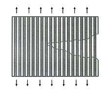
The high fracture toughness or crack resistance mentioned above is a result of the following mechanism: under load the ceramic matrix cracks, like any ceramic material, at an elongation of about 0.05%. In CMCs the embedded fibres bridge these cracks (see picture). This mechanism works only when the matrix can slide along the fibres, which means that there must be a weak bond between the fibres and matrix. A strong bond would require a very high elongation capability of the fibre bridging the crack, and would result in a brittle fracture, as with conventional ceramics. The production of CMC material with high crack resistance requires a step to weaken this bond between the fibres and matrix. This is achieved by depositing a thin layer of pyrolytic carbon or boron nitride on the fibres, which weakens the bond at the fibre/matrix interface (sometimes "interface"), leading to the fibre pull-out at crack surfaces, as shown in the SEM picture at the top of this article. In oxide-CMCs, the high porosity of the matrix is sufficient to establish the weak bond.
Properties under tensile and bending loads, crack resistance
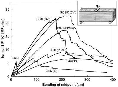
Legend: SiSiC: conventional SiSiC, SiCSiC(CVI) and CSiC(CVI): SiC/SiC and C/SiC manufactured in CVI processes, CSiC(95) und CSiC(93): C/SiC manufactured by the LPI-method, Ox(PP): oxide ceramic composite, CSiC(Si): C/SiC manufactured via the LSI process.
The influence and quality of the fibre interface can be evaluated through mechanical properties. Measurements of the crack resistance were performed with notched specimens (see figure) in so-called single-edge-notch-bend (SENB) tests. In fracture mechanics, the measured data (force, geometry and crack surface) are normalized to yield the so-called stress intensity factor (SIF), KIc. Because of the complex crack surface (see figure at the top of this article) the real crack surface area can not be determined for CMC materials. The measurements therefore use the initial notch as the crack surface, yielding the formal SIF shown in the figure. This requires identical geometry for comparing different samples. The area under these curves thus gives a relative indication of the energy required to drive the crack tip through the sample (force times path length gives energy). The maxima indicate the load level necessary to propagate the crack through the sample. Compared to the sample of conventional SiSiC ceramic, two observations can be made:
- All tested CMC materials need up to several orders of magnitude more energy to propagate the crack through the material.
- The force required for crack propagation varies between different types of CMCs.
| Type of material | Al2O3/Al2O3 | Al2O3 | CVI-C/SiC | LPI-C/SiC | LSI-C/SiC | SiSiC |
|---|---|---|---|---|---|---|
| Porosity (%) | 35 | <1 | 12 | 12 | 3 | <1 |
| Density (g/cm3) | 2.1 | 3.9 | 2.1 | 1.9 | 1.9 | 3.1 |
| Tensile strength (MPa) | 65 | 250 | 310 | 250 | 190 | 200 |
| Elongation (%) | 0.12 | 0.1 | 0.75 | 0.5 | 0.35 | 0.05 |
| Young's modulus (GPa) | 50 | 400 | 95 | 65 | 60 | 395 |
| Flexural strength (MPa) | 80 | 450 | 475 | 500 | 300 | 400 |
In the table, CVI, LPI, and LSI denote the manufacturing process of the C/SiC-material. Data of the oxide CMC and SiSiC are taken from manufacturer data sheets. Tensile strength of SiSiC and Al2O3 were calculated from measurements of elongation to fracture and Young's modulus, since generally only bending strength data are available for those ceramics. Averaged values are given in the table, and significant differences, even within one manufacturing route, are possible.
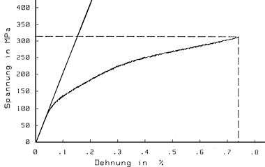
Tensile tests of CMCs usually show nonlinear stress-strain curves, which look as if the material deforms plastically. It is called quasi-plastic, because the effect is caused by the microcracks, which are formed and bridged with increasing load. Since the Young's modulus of the load-carrying fibres is generally lower than that of the matrix, the slope of the curve decreases with increasing load.
Curves from bending tests look similar to those of the crack resistance measurements shown above.
The following features are essential in evaluating bending and tensile data of CMCs:
- CMC materials with a low matrix content (down to zero) have a high tensile strength (close to the tensile strength of the fibre), but low bending strength.
- CMC materials with a low fibre content (down to zero) have a high bending strength (close to the strength of the monolithic ceramic), but no elongation beyond 0.05% under tensile load.
The primary quality criterion for CMCs is the crack resistance behaviour or fracture toughness.
Other mechanical properties
In many CMC components the fibres are arranged as 2-dimensional (2D) stacked plain or satin weave fabrics. Thus the resulting material is anisotropic or, more specifically, orthotropic. A crack between the layers is not bridged by fibres. Therefore, the interlaminar shear strength (ILS) and the strength perpendicular to the 2D fiber orientation are low for these materials. Delamination can occur easily under certain mechanical loads. Three-dimensional fibre structures can improve this situation (see micrograph above).
| Material | CVI-C/SiC | LPI-C/SiC | LSI-C/SiC | CVI-SiC/SiC |
|---|---|---|---|---|
| Interlaminar shear strength (MPa) | 45 | 30 | 33 | 50 |
| Tensile strength vertical to fabric plane (MPa) | 6 | 4 | – | 7 |
| Compressive strength vertical to fabric plane (MPa) | 500 | 450 | – | 500 |
The compressive strengths shown in the table are lower than those of conventional ceramics, where values above 2000 MPa are common; this is a result of porosity.
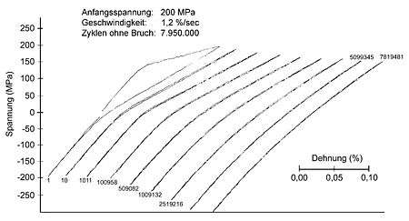
The composite structure allows high dynamical loads. In the so-called low-cycle-fatigue (LCF) or high-cycle-fatigue (HCF) tests the material experiences cyclic loads under tensile and compressive (LCF) or only tensile (HCF) load. The higher the initial stress the shorter the lifetime and the smaller the number of cycles to rupture. With an initial load of 80% of the strength, a SiC/SiC sample survived about 8 million cycles (see figure).
The Poisson's ratio shows an anomaly when measured perpendicular to the plane of the fabric, because interlaminar cracks increase the sample thickness.
Thermal and electrical properties
The thermal and electrical properties of the composite are a result of its constituents, namely fibres, matrix and pores as well as their composition. The orientation of the fibres yields anisotropic data. Oxide CMCs are very good electrical insulators, and because of their high porosity their thermal insulation is much better than that of conventional oxide ceramics.
The use of carbon fibres increases the electrical conductivity, provided the fibres contact each other and the voltage source. Silicon carbide matrix is a good thermal conductor. Electrically, it is a semiconductor, and its resistance therefore decreases with increasing temperature. Compared to (poly)crystalline SiC, the amorphous SiC fibres are relatively poor conductors of heat and electricity.
| Material | CVI-C/SiC | LPI-C/SiC | LSI-C/SiC | CVI-SiC/SiC | SiSiC |
|---|---|---|---|---|---|
| Thermal conductivity (p) [W/(m·K)] | 15 | 11 | 21 | 18 | >100 |
| Thermal conductivity (v) [W/(m·K)] | 7 | 5 | 15 | 10 | >100 |
| Linear expansion (p) [10−6·1/K] | 1.3 | 1.2 | 0 | 2.3 | 4 |
| Linear expansion (v) [10−6·1/K] | 3 | 4 | 3 | 3 | 4 |
| Electrical resistivity (p) [Ω·cm] | – | – | – | – | 50 |
| Electrical resistivity (v) [Ω·cm] | 0.4 | – | – | 5 | 50 |
Comments for the table: (p) and (v) refer to data parallel and vertical to fibre orientation of the 2D-fiber structure, respectively. LSI material has the highest thermal conductivity because of its low porosity – an advantage when using it for brake discs. These data are subject to scatter depending on details of the manufacturing processes.
Conventional ceramics are very sensitive to thermal stress because of their high Young's modulus and low elongation capability. Temperature differences and low thermal conductivity create locally different elongations, which together with the high Young's modulus generate high stress. This results in cracks, rupture and brittle failure. In CMCs, the fibres bridge the cracks, and the components show no macroscopic damage, even if the matrix has cracked locally. The application of CMCs in brake disks demonstrates the effectiveness of ceramic composite materials under extreme thermal shock conditions.
Corrosion properties
Data on the corrosion behaviour of CMCs are scarce except for oxidation at temperatures above 1000 °C. These properties are determined by the constituents, namely the fibres and matrix. Ceramic materials in general are very stable to corrosion. The broad spectrum of manufacturing techniques with different sintering additives, mixtures, glass phases and porosities are crucial for the results of corrosion tests. Less impurities and exact stoichiometry lead to less corrosion. Amorphous structures and non-ceramic chemicals frequently used as sintering aids are starting points of corrosive attack.[14][15]
- Alumina
Pure alumina shows excellent corrosion resistivity against most chemicals. Amorphous glass and silica phases at the grain boundaries determine the speed of corrosion in concentrated acids and bases and result in creep at high temperatures. These characteristics limit the use of alumina. For molten metals, alumina is used only with gold and platinum.
- Alumina fibres
These fibres demonstrate corrosion properties similar to alumina, but commercially available fibres are not very pure and therefore less resistant. Because of creep at temperatures above 1000 °C, there are only few applications for oxide CMCs.
- Carbon
The most significant corrosion of carbon occurs in presence of oxygen above about 500 °C. It burns to form carbon dioxide and/or carbon monoxide. It also oxidises in strong oxidizing agents like concentrated nitric acid. In molten metals it dissolves and forms metal carbides. Carbon fibres do not differ from carbon in their corrosion behaviour.
- Silicon carbide
Pure silicon carbide is one of the most corrosion-resistant materials. Only strong bases, oxygen above about 800 °C, and molten metals react with it to form carbides and silicides. The reaction with oxygen forms SiO2 and CO2, whereby a surface layer of SiO2 slows down subsequent oxidation (passive oxidation). Temperatures above about 1600 °C and a low partial pressure of oxygen result in so-called active oxidation, in which CO, CO2 and gaseous SiO are formed causing rapid loss of SiC. If the SiC matrix is produced other than by CVI, corrosion-resistance is not as good. This is a consequence of porosity in the amorphous LPI, and residual silicon in the LSI-matrix.
- Silicon carbide fibres
Silicon carbide fibres are produced via pyrolysis of organic polymers, and therefore their corrosion properties are similar to those of the silicon carbide found in LPI-matrices. These fibres are thus more sensitive to bases and oxidizing media than pure silicon carbide.
Applications
CMC materials overcome the major disadvantages of conventional technical ceramics, namely brittle failure and low fracture toughness, and limited thermal shock resistance. Therefore, their applications are in fields requiring reliability at high-temperatures (beyond the capability of metals) and resistance to corrosion and wear. These include:
- Heat shield systems for space vehicles, which are needed during the re-entry phase, where high temperatures, thermal shock conditions and heavy vibration loads take place.
- Components for high-temperature gas turbines such as combustion chambers, stator vanes and turbine blades.
- Components for burners, flame holders, and hot gas ducts, where the use of oxide CMCs has found its way.
- Brake disks and brake system components, which experience extreme thermal shock (greater than throwing a glowing part of any material into water).
- Components for slide bearings under heavy loads requiring high corrosion and wear resistance.
In addition to the foregoing, CMCs can be used in applications, which employ conventional ceramics or in which metal components have limited lifetimes due to corrosion or high temperatures.
Developments for applications in space
During the re-entry phase of space vehicles, the heat shield system is exposed to temperatures above 1500 °C for a few minutes. Only ceramic materials are able to survive such conditions without significant damage, and among ceramics only CMCs can adequately handle thermal shocks. The development of CMC-based heat shield systems promises the following advantages:
- Reduced weight
- Higher load carrying capacity of the system
- Reusability for several re-entries
- Better steering during the re-entry phase with CMC flap systems

In these applications the high temperatures preclude the use of oxide fibre CMCs, because under the expected loads the creep would be too high. Amorphous silicon carbide fibres lose their strength due to re-crystallization at temperatures above 1250 °C. Therefore, carbon fibres in a silicon carbide matrix (C/SiC) are used in development programs for these applications. The European program HERMES of ESA, started in the 1980s and for financial reasons abandoned in 1992, has produced first results. Several follow-up programs focused on the development, manufacture, and qualification of nose cap, leading edges and steering flaps for the NASA space vehicle X-38.[16][17]

This development program has qualified the use of C/SiC bolts and nuts,[18] and the bearing system of the flaps. The latter were ground-tested at the DLR in Stuttgart, Germany, under expected conditions of the re-entry phase: 1600 °C, 4 tonnes load, oxygen partial pressure similar to re-entry conditions, and simultaneous bearing movements of four cycles per second. A total of five re-entry phases was simulated.[19] Furthermore, oxidation protection systems were developed and qualified to prevent burnout of the carbon fibres. After mounting of the flaps, mechanical ground tests were performed successfully by NASA in Houston, Texas, US. The next test – a real re-entry of the unmanned vehicle X-38 – was cancelled for financial reasons. One of the space shuttles would have brought the vehicle into orbit, from where it would have returned to the Earth.
These qualifications were promising for only this application. The high-temperature load lasts only around 20 minutes per re-entry, and for reusability, only about 30 cycles would be sufficient. For industrial applications in hot gas environment, though, several hundred cycles of thermal loads and up to many thousands hours of lifetime are required.
The Intermediate Experimental Vehicle (IXV), a project initiated by ESA[20] in 2009, is Europe's first lifting body reentry vehicle. Developed by Thales Alenia Space, the IXV is scheduled to make its first flight in 2014 on the fourth Vega mission (VV04) over the Gulf of Guinea. More than 40 European companies contributed to its construction. The thermal protection system for the underside of the vehicle, comprising the nose, leading edges and lower surface of the wing, were designed and made by Herakles[21] using a ceramic matrix composite (CMC), carbon/silicon-carbide (C/SiC). These components will function as the vehicle's heat shield during its atmospheric reentry.[22]
Developments for gas turbine components
The use of CMCs in gas turbines would permit higher turbine inlet temperatures, which would improve turbine efficiency. Because of the complex shape of stator vanes and turbine blades, the development was first focused on the combustion chamber. In the US, a combustor made of SiC/SiC with a special SiC fiber of enhanced high-temperature stability was successfully tested for 15,000 hours.[23] SiC oxidation was substantially reduced by the use of an oxidation protection coating consisting of several layers of oxides.[24] The engine collaboration between General Electric and Rolls-Royce is studying the use of CMC stator vanes in the hot section of the F136 turbofan engine, an engine which failed to beat the Pratt and Whitney F-135 for use in the Joint Strike Fighter. The engine joint venture, CFM International is also considering the use of CMC parts to reduce weight in its Leap-X demonstrator engine program, which is aimed at providing next-generation turbine engines for narrow-body airliners. CMC parts are also being studied for stationary applications in both the cold and hot sections of the engines, since stresses imposed on rotating parts would require further development effort. Generally, a successful application in turbines still needs a lot of technical and cost reduction work for all high-temperature components to justify the efficiency gain. Furthermore, cost reduction for fibers, manufacturing processes and protective coatings is essential.
Application of oxide CMC in burner and hot gas ducts
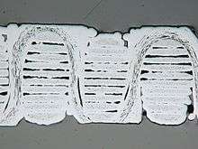
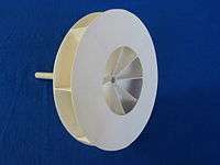
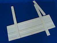
Oxygen-containing gas at temperatures above 1000 °C is rather corrosive for metal and silicon carbide components. Such components, which are not exposed to high mechanical stress, can be made of oxide CMCs, which can withstand temperatures up to 1200 °C. The gallery below shows the flame holder of a crisp bread bakery as tested after for 15,000 hours, which subsequently operated for a total of more than 20,000 hours.[25]
 |
 |
 |
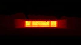 |
| Oxide CMC flame holder | Ventilator for hot gases | Lifting gate, oxide CMC | Lifting gate in the field |
Flaps and ventilators circulating hot, oxygen-containing gases can be fabricated in the same shape as their metal equivalents. The lifetime for these oxide CMC components is several times longer than for metals, which often deform. A further example is an oxide CMC lifting gate for a sintering furnace, which has survived more than 260,000 opening cycles.[26]
Application in brake disk
Carbon/carbon (C/C) materials have found their way into the disk brakes of racing cars and aeroplanes, and C/SiC brake disks manufactured by the LSI process were qualified and are commercially available for luxury vehicles. The advantages of these C/SiC disks are:
- Very little wear, resulting in lifetime use for a car with a normal driving load of 300,000 km, is forecast by manufacturers.
- No fading is experienced, even under high load.
- No surface humidity effect on the friction coefficient shows up, as in C/C brake disks.
- The corrosion resistance, for example to the road salt, is much better than for metal disks.
- The disk mass is only 40% of a metal disk. This translates into less unsprung and rotating mass.
The weight reduction improves shock absorber response, road-holding comfort, agility, fuel economy, and thus driving comfort.[27]
The SiC-matrix of LSI has a very low porosity, which protects the carbon fibres quite well. Brake disks do not experience temperatures above 500 °C for more than a few hours in their lifetime. Oxidation is therefore not a problem in this application. The reduction of manufacturing costs will decide the success of this application for middle-class cars.
Application in slide bearings

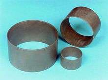
Conventional SiC, or sometimes the less expensive SiSiC, have been used successfully for more than 25 years in slide or journal bearings of pumps.[28] The pumped liquid itself provides the lubricant for the bearing. Very good corrosion resistance against practically all kinds of media, and very low wear and low friction coefficients are the basis of this success. These bearings consist of a static bearing, shrink-fitted in its metallic environment, and a rotating shaft sleeve, mounted on the shaft. Under compressive stress the ceramic static bearing has a low risk of failure, but a SiC shaft sleeve does not have this situation and must therefore have a large wall thickness and/or be specially designed. In large pumps with shafts 100–350 mm in diameter, the risk of failure is higher due to the changing requirements on the pump performance – for example, load changes during operation. The introduction of SiC/SiC as a shaft sleeve material has proven to be very successful. Test rig experiments showed an almost triple specific load capability of the bearing system with a shaft sleeve made of SiC/SiC, sintered SiC as static bearing, and water at 80 °C as lubricant.[29] The specific load capacity of a bearing is usually given in W/mm2 and calculated as a product of the load (MPa), surface speed of the bearing (m/s) and friction coefficient; it is equal to the power loss of the bearing system due to friction.
In boiler feedwater pumps of power stations,[29] which pump several thousand cubic meters of hot water to a level of 2000 m, and in tubular casing pumps [30] for water works or sea water desalination plants (pumping up to 40,000 m3 to a level of around 20 m) this slide bearing concept, namely SiC/SiC shaft sleeve and SiC bearing, has been used since 1994. A picture of such shaft sleeves is shown at the top of this article.
This bearing system has been tested in pumps for liquid oxygen, for example in oxygen turbopumps for thrust engines of space rockets, with the following results. SiC and SiC/SiC are compatible with liquid oxygen. In an auto-ignition test according to the French standard NF 28-763, no auto-ignition was observed with powdered SiC/SiC in 20 bar pure oxygen at temperatures up to 525 °C. Tests have shown that the friction coefficient is half, and wear one fiftieth of standard metals used in this environment.[31] A hydrostatic bearing system (see picture) has survived several hours at a speed up to 10,000 revolutions per minute, various loads, and 50 cycles of start/stop transients without any significant traces of wear.[32]
Other applications and developments
- Thrust control flaps for military jet engines [33]
- Components for fusion and fission reactors [34]
- Friction systems for various applications [35]
- Nuclear applications[36]
References
- ↑ T. R. Cooke (1991). "Inorganic fibres- A Literature Review". Journal of the American Ceramic Society. 74: 2959–2978. doi:10.1111/j1151-2916.1991.tb04289.x.
- ↑ K. Kumagawa; H. Yamaoka; M Shibuysa; T. Ymamura (1998). "Fabrication and mechanical properties of new improved Si-M-C-(O) Tyranno fiber". Ceramic Engineering and Science Proceedings. 19A: 65–72. doi:10.1002/9780470294482.ch8.
- ↑ R. Naslain; F. Langlais; R. Fedou (1989). "The CVI-Processing of Ceramic Matrix Composites". Journal de Phys. Colloque. 50: C191-C207. doi:10.1051/jphyscol:1989526.
- ↑ K. J. Probst; T. M. Besman; D. P. Stinton; R. A. Lowden; T. JK. Anderson; T. L. Starr (1999). "Recent advances in forced-flow, thermal-gradient CVI for refractory composites". Surface and Coatings Technology. 120-121: 250–258. doi:10.1016/S0257-8972(99)00459-4.
- ↑ G. Ziegler; I. Richter; D. Suttor (1999). "Fiber-reinforced composites with polymer-derived matrix: processing, matrix formation and properties". Composites Part A: Applied Science and Manufacturing. 30: 411–417. doi:10.1016/S1359-835X(98)00128-6.
- ↑ M. Kotani; Y. Katoh; A. Khyama (2003). "Fabrication and Oxidation-Resistance Property of Allylhydridopolycarbosilane-derived SiC/SiC Composites". Journal of the Ceramic Society of Japan. 111: 300–307. doi:10.2109/jcersj.111.300.
- ↑ R. M. Rocha; C. A. A. Cairo; M. L. A. Graca (2006). "Formation of carbon fibre-reinforced ceramic matrix composites with ploysiloxane/silicon derived matrix". Materials Science and Engineering, Part A. 437: 268–273. doi:10.1016/j.msea.2006.08.102.
- ↑ W. Krenkel (2008). "Cost Effective Processing of CMC Composites by Melt Infiltration (LSI-Process)". Ceramic Engineering and Science Proceedings. 22: chapter 52. doi:10.1002/9780470294680.ch52.
- ↑ R. A. Simon (2005). "Progress in Processing and Performance of Porous-Matrix Oxide/Oxide Composites". International Journal of Applied Ceramic Technology. 2: 141–149. doi:10.1111/j.1744-7402.2005.02016.x.
- ↑ W. Pritzkow (2001). ""Keramikblech" properties and applications". Proceedings of the 4th International Conference on High Temperature Ceramic matrix Composites (HT-CMC4) in Munich, Wiley-VCH: 681. doi:10.1115/GT2002-30585.
- ↑ E. Stoll; P. Mahr; H. G. Krueger; H. Kern; R. Boccaccini (2005). "Progress in the Electrophoretic Deposition Technique to Infiltrate Oxide Fibre Mats for Fabrication of Ceramic Matrix Composites". Key Engineering Materials. 314: 195–200. doi:10.4028/www.scientific.net/KEM.314.195.
- ↑ Y. Bao; P. S. Nicholson; F. Zok (2007). "Constant Current Electrophoretic Infiltration Deposition of Fiber-Reinforced Ceramic Composites". Journal of the American Ceramic Society. 90: 1063–1070. doi:10.1111/j.1551--2916.2007.01504.x.
- ↑ M. Kuntz, Ceramic Matrix Composites, cfi/Bericht der DKG, vol. 49, No. 1, 1992, p. 18
- ↑ F. Schröder (ed.): Gmelin Handbook of Inorganic Chemistry, 8th edition, Silicon, suppl. vol. B3, Silicon Carbide, Part 2, Springer Verlag, 1986, pp. 322–397
- ↑ V. A. Lavrenko: Corrosion of High-Performance Ceramics, Springer-Verlag, 1992 ISBN 3-540-55316-9
- ↑ H. Pfeiffer: Ceramic Body Flap for X-38 and CRV. 2nd International Symposium on Atmospheric Re-entry Vehicles and Systems, Arcachon, France, March 2001
- ↑ H. Pfeiffer, K. Peetz: All-Ceramic Body Flap Qualified for Space Flight on the X-38. 53rd International Astronautical Congress, Houston, Texas, US, October 2002, Paper IAF-02-I.6.b.01
- ↑ H. Lange, M. Dogigli, M. Bickel: Ceramic Fasteners for High Temperature Applications. 5th International Conference on Joining: Ceramics, Glas and Metal, Jena, May 1997, DVS-Berichte Band 184, Deutscher Verlag für Schweißtechnik, p. 55, ISBN 3-87155-489-8
- ↑ M. Dogigli, H. Weihs, K. Wildenrotter, H. Lange: New High-Temperature Ceramic Bearing for Space Vehicles. 51st International Astronautical Congress, Rio de Janeiro, Brazil, October 2000, Paper IAF-00-I.3.04
- ↑ http://www.esa.int/For_Media/Press_Releases/ESA_activities_in_2014_of_interest_to_media
- ↑ http://www.herakles.com/medias-et-evenements/actualites/herakles-a-bord-de-l-ixv
- ↑ http://www.jeccomposites.com/news/composites-news/bouclier-thermique-en-composite-matrice-ceramique-pour-rentree-atmospherique
- ↑ N. Miriyala; J. Kimmel; J. Price; H. Eaton; G. Linsey; E. Sun (2002). "The evaluation of CFCC Liners After Field Testing in a Gas Turbine – III" (PDF): 109–118. doi:10.1115/GT2002-30585. ISBN 0-7918-3609-6.
- ↑ K.L. More; P.F. Tortorelli; L.R. Walker; J.B. Kimmel; N. Miriyala; J.R. Price; H.E. Eaton; E. Y. Sun; G.D. Linsey (2002). "Volume 4: Turbo Expo 2002, Parts A and B" (PDF): 155–162. doi:10.1115/GT2002-30630. ISBN 0-7918-3609-6.
- ↑ W.E.C. Pritzkow: Keramikblech, ein Werkstoff für höchste Ansprüche. cfi Sonderausgabe zum DKG-DGM Symposium Hochleistungskeramik 2005, W. Krenkel (Ed.), ISSN 0173-9913, p. 40
- ↑ W.E.C. Pritzkow: Oxide-Fibre-Reinforced Ceramics. cfi/Ber. DKG 85 (2008) No. 12, p.E1
- ↑ W. Krenkel, R. Renz, CMCs for Friction Applications, in Ceramic Matrix Composites, W. Krenkel editor, Wiley-VCH, 2008. ISBN 978-3-527-31361-7, p. 396
- ↑ W. J. Bartz (ed.): Keramiklager, Werkstoffe – Gleit- und Wälzlager – Dichtungen. Handbuch der Tribologie und Schmierungstechnik. Vol. 12. Expert Verlag, Renningen 2003. ISBN 3-8169-2050-0
- 1 2 K. Gaffal, A.-K. Usbeck, W. Prechtl: Neue Werkstoffe ermöglichen innovative Pumpenkonzepte für die Speisewasserförderung in Kesselanlagen. VDI-Berichte Nr. 1331, VDI-Verlag, Düsseldorf, 1997, p. 275
- ↑ W. Kochanowski, P. Tillack: New Pump Bearing Materials Prevent Damage to Tubular Casing Pumps. VDI-Berichte Nr. 1421, VDI-Verlag, Düsseldorf, 1998, p. 227
- ↑ J.L. Bozet, M. Nelis, M. Leuchs, M. Bickel: Tribology in Liquid Oxygen of SiC/SiC Ceramic Matrix Composites in Connection with the Design of Hydrostatic Bearing. Proceedings of the 9th European Space Mechanisms & Tribology Symposium (ESMAT), Liège, Belgium, September 2001, ESA document SP-480, p. 35
- ↑ M. Bickel, M. Leuchs, H. Lange, M. Nelis, J.L. Bozet: Ceramic Journal Bearings in Cryogenic Turbo-Pumps. 4th International Conference on Launcher Technology – Space Launcher Liquid Propulsion, Liège, Belgium, December 2002, Paper #129
- ↑ P. Boullon; G. Habarou; P.C. Spriet; J.L. Lecordix; G.C. Ojard; G.D. Linsey; D.T. Feindel (2002). "Volume 4: Turbo Expo 2002, Parts A and B": 15–21. doi:10.1115/GT2002-30458. ISBN 0-7918-3609-6.
- ↑ B. Riccardi; L. Giancarli; A. Hasegawa; Y. Katoh; A. Kohyama; R.H. Jones; L.L Snead (2004). "Issues and Advances in SiCf/SiC Composite development for Fusion Reactors". Journal of Nuclear Materials. 329–333: 56–65. Bibcode:2004JNuM..329...56R. doi:10.1016/j.jnucmat.2004.04.002.
- ↑ W. Krenkel (ed.): Ceramic Matrix Composites. Wiley-VCH, Weinheim 2008. ISBN 978-3-527-31361-7, p. 38
- ↑ N.P. Bansal, J.Lamon (ed.): "Ceramic Matrix Composites: Materials, Modeling and Technology". Wiley, Hoboken, NJ 2015. ISBN 978-1-118-23116-6, p. 609
Further reading
- J. Kriegesmann (ed.): DKG – Technische Keramische Werkstoffe. HvB-Verlag, Ellerau 2005. ISBN 978-3-938595-00-8
- W. Krenkel (ed.): Ceramic Matrix Composites. Wiley-VCH, Weinheim 2008. ISBN 978-3-527-31361-7
- N. P. Bansal (ed.): "Handbook of Ceramic Composites". Kluwer Academic Publishers, Boston 2005. ISBN 1-4020-8133-2
- N. P. Bansal and J. Lamon (eds.): "Ceramic Matrix Composites: Materials, Modeling and Technology". Wiley, Hoboken, NJ 2015. ISBN 978-1-118-23116-6