Cephalometric analysis
Cephalometric analysis is the clinical application of cephalometry. It is analysis of the dental and skeletal relationships in the head.[1] It is frequently used by dentists, orthodontists, and oral and maxillofacial surgeons as a treatment planning tool.[2]
Two of the more popular methods of analysis used in orthodontology are the Steiner analysis, named after Cecil C. Steiner, and the McNamara analysis, named after James A. McNamara.[3] There are other methods as well, including the Ricketts analysis.[4]
Cephalometric radiographs
Cephalometric analysis depends on cephalometric radiography to study relationships between bony and soft tissue landmarks and can be used to diagnose facial growth abnormalities prior to treatment, in the middle of treatment to evaluate progress or at the conclusion of treatment to ascertain that the goals of treatment have been met.[5] A Cephalometric radiograph is a radiograph of the head taken in a Cephalometer (Cephalostat) that is a head-holding device introduced in 1931 by Birdsall Holly Broadbent Sr. in USA[6] and by H. Hofrath
in Germany. The Cephalometer is used to obtain standardized and comparable craniofacial images on radiographic films.
Lateral cephalometric radiographs
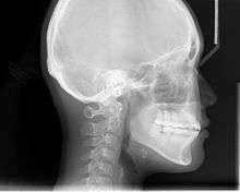
Lateral cephalometric radiograph is a radiograph of the head taken with the x-ray beam perpendicular to the patient's sagittal plane. Natural head position is a standardized orientation of the head that is reproducible for each individual and is used as a means of standardization during analysis of dentofacial morphology both for photos and radiographs. The concept of natural head position was introduced by C. F. A. Moorrees and M. R Kean in 1958 and now is a common method of head orientation for cephalometric radiography.
Registration of the head in its natural position while obtaining a cephalogram has the advantage that an extracranial line (the true vertical or a line perpendicular to that) can be used as a reference line for cephalometric analysis, thus bypassing the difficulties imposed by the biologic variation of intracranial reference lines. True vertical is an external reference line, commonly provided by the image of a free-hanging metal chain on the cephalostat registering on the film or digital cassette during exposure. The true vertical line offers the advantage of no variation (since it is generated by gravity) and is used with radiographs obtained in natural head position.
Posteroanterior (P-A) cephalometric radiograph
A radiograph of the head taken with the x-ray beam perpendicular to the patient’s coronal plane with the x-ray source behind the head and the film cassette in front of the patient’s face.
Cephalometric tracing
A Cephalometric tracing is an overlay drawing produced from a cephalometric radiograph by digital means and a computer program or by copying specific outlines from it with a lead pencil onto acetate paper, using an illuminated view-box. Tracings are used to facilitate cephalometric analysis, as well as in superimpositions, to evaluate treatment and growth changes.
Cephalometric landmarks
The following are important cephalometric landmarks.[definition needed] (Sources: Proffit;[7] others.)
Landmark points can be joined by lines to form axes, vectors, angles, and planes (a line between 2 points can define a plane by projection). For example, the sella (S) and the nasion (N) together form the sella-nasion line (SN or S-N). A prime symbol (′) usually indicates the point on the skin's surface that corresponds to a given bony landmark (for example, nasion (N) versus skin nasion (N′).
| Landmark name | Landmark symbol | Comments |
|---|---|---|
| A point (subspinale) | A | Most concave point of anterior maxilla |
| A point–nasion–B point angle | ANB | Average of 2° ± 2° |
| B point (supramentale) | B | Most concave point on mandibular symphysis |
| basion | Ba | Most anterior point on foramen magnum |
| anterior nasal spine | ANS | Anterior point on maxillary bone |
| articulare | Ar | Junction between inferior surface of the cranial base and the posterior border of the ascending rami of the mandible |
| Bolton point | Highest point on the retrocondylar fossa of the occipital bone | |
| cheilion | Ch | Corner of oral cavity |
| chresta philtri | Chp | Head of nasal filter |
| condylion | Most posterior/superior point on the condyle of mandible | |
| dacryon | dac | Point of junction of maxillary bone, lacrimal bone, and frontal bone |
| endocanthion | En | Point at which inner ends of upper and lower eyelids meet |
| exocanthion (synonym, ectocanthion) | Ex | Point at which outer ends of upper and lower eyelids meet |
| Frankfort horizontal plane (synonym, Frankfurt plane) | Po-Or | Po-Or line projected to form a plane |
| frontotemporal | Ft | Most medial point on the temporal crest |
| glabella | G' | Most prominent point in the median sagittal plane between the supraorbital ridges |
| gnathion | Gn | Point located perpendicular on mandibular symphysis midway between pogonion and menton |
| gonion | Go | Most posterior inferior point on angle of mandible. Can also be constructed by bisecting the angle formed by intersection of mandibular plane and ramus of mandible |
| key ridges | Posterior vertical portion and inferior curvature of left and right zygomatic bones | |
| labial inferior | Li | Point denoting vermilion border of lower lip in midsagittal plane |
| labialis superior | Ls | Point denoting vermilion border of upper lip |
| lower incisor | L1 | Line connecting incisal edge and root apex of the most prominent mandibular incisor |
| menton | Me | Lowest point on mandibular symphysis |
| soft tissue menton | Me′ | Lowest point on soft tissue over mandible |
| nasion | N | Most anterior point on frontonasal suture |
| soft tissue nasion | N′ | Point on soft tissue over nasion |
| odontale | Highest point on second vertebra | |
| orbitale | Or | Most inferior point on margin of orbit |
| opisthion | Op | Posterior point of foramen magnum |
| pogonion | Pg | Most anterior point of mandibular symphysis |
| soft tissue pogonion | Pg′ | Soft tissue over pogonion |
| porion | Po | Most superior point of outline of external auditory meatus |
| machine porion | Superior-most point of the image of the ear rod | |
| posterior nasal spine | PNS | Posterior limit of bony palate or maxilla |
| pronasale (synonyms, pronasal or pronasion) | Prn | Soft tissue point on tip of nose |
| prosthion (supradentale, superior prosthion) | Pr | The most inferior anterior point on the maxillary alveolar process between the central incisors |
| PT point | PT | Point at junction between Ptm and foramen rotundum (at 11 o'clock from Ptm) |
| pterygomaxillary fissure | Ptm | Point at base of fissure where anterior and posterior wall meet. Anterior wall represents posterior surface of maxillary tuberosity |
| registration point | A reference point for superimposition of ceph tracings | |
| sella (that is, sella turcica) | S | Midpoint of sella turcica |
| sphenoethmoidal suture | SE | the cranial suture between the sphenoid bone and the ethmoid bone |
| sella-nasion line | SN or S-N | A line connecting sella to nasion |
| sella–nasion–A point angle | SNA or S-N-A | Average of 82 degrees with +/- of 2 degrees |
| sella–nasion–B point angle | SNB or S-N-B | Average of 80 degrees with +/- of 2 degrees |
| sublabialis | Sl | |
| subnasale (synonyms, subnasal or subnasion) | Sn | In the midline, the junction where base of the columella of the nose meets the upper lip |
| stomion inferius | Sti | Highest midline point of lower lip |
| stomion superius | Sts | Highest midline point of upper lip |
| throat point | Junction of inferior border of mandible and throat | |
| tragion | T′ | Notch above the tragus of the ear where the upper edge of the cartilage disappears into the skin of the face |
| trichion | Tr | Midline of hairline |
| upper incisor | U1 | A line connecting the incisal edge and root apex of the most prominent maxillary incisor |
| xi point | Xi | An approximate point for inferior alveolar foramen |
Classification of analyses
The basic elements of analysis are angles and distances. Measurements (in degrees or millimetres) may be treated as absolute or relative, or they may be related to each other to express proportional correlations. The various analyses may be grouped into the following:
- Angular – dealing with angles,
- Linear – dealing with distances and lengths,
- Coordinate – involving the Cartesian (X, Y) or even 3-D planes,
- Arcial – involving the construction of arcs to perform relational analyses.
These in turn may be grouped according to the following concepts on which normal values have been based:
- Mononormative analyses: averages serve as the norms for these and may be arithmetical (average figures) or geometrical (average tracings). E.g. Bolton Standards.
- Multinormative: for these a whole series of norms are used, with age and sex taken into account, e.g. Bolton Standards.
- Correlative: used to assess individual variations of facial structure to establish their mutual relationships, e.g. Sassouni’s arcial analysis.
Cephalometric angles
According to the Steiner's analysis:
- ANB (A point, nasion, B point) indicates whether the skeletal relationship between the maxilla and mandible is a normal skeletal class I (+2 degrees), a skeletal Class II (+4 degrees or more), or skeletal class III (0 or negative) relationship.
- SNA (sella, nasion, A point) indicates whether or not the maxilla is normal, prognathic, or retrognathic.
- SNB (sella, nasion, B point) indicates whether or not the mandible is normal, prognathic, or retrognathic.
SNA and SNB is important to determine what type of intervention (on maxilla, mandible or both) is appropriate. These angles, however are influenced also by the vertical height of the face and a possible abnormal positioning of nasion.[7] By using a comparative set of angles and distances, measurements can be related to one another and to normative values to determine variations in a patient’s facial structure.[8]
List of Cephalometric Analysis
Steiner's Analysis
| Name | Description | Normal | Standard Deviation |
|---|---|---|---|
| Skeletal | |||
| SNA (°) | Sella-Nasion to A Point Angle | 82 | +/- 2 |
| SNB (°) | Sella-Nasion to B Point Angle | 80 | +/- 2 |
| ANB (°) | A point to B Point Angle | 2 | +/- 2 |
| Occlusal Plane to SN (°) | SN to Occlusal Plane Angle | 14 | |
| Mandibular Plane (°) | SN to Mandibular Plane Angle | 32 | |
| Dental | |||
| U1-NA (degree) | Angle between upper Incisor to NA Line | 22 | |
| U1-NA (mm) | Distance from Upper Incisor to NA Line | 4 | |
| L1-NB (degree) | Angle between lower Incisor to NB Line | 25 | |
| L1-NB (mm) | Distance from lower Incisor to NB Line | 4 | |
| U1-L1 (°) | Upper Incisor to Lower Incisor Angle | 130 | |
| L1-Chin (mm) | Distance from distal surface of lower incisor to N-B Line | 4 | |
| Soft Tissue | |||
| S Line | Line formed by connecting Soft Tissue Pogonion and middle of an S formed by lower border of the nose | Ideally, lips both lips should touch the S line |
Wits Analysis
Wits is short for Witwatersrand which is a University in South Africa. Jacobsen in 1975 published an article called "The Wits appraisal of jaw disharmony". This analysis was created as a diagnostic aid to measure the disharmony between the AP degree. The ANB angle can be affected by multitude of environmental factors such as: 1. Patient's age where ANB has tendency to reduced with age 2. Change in position of nasion as pubertal growth takes place 3. Rotational effect of jaws 4. Degree of facial Prognathism 5. Therefore, it measured the AP positions of the jaw to each other. This analysis calls for 1. Drawing an Occlusal Plane through the overlapping cusps of Molars and Premolars. 2. Draw perpendicular lines connecting A point and B Point to the Occlusal Plane 3. Label the points as AO and BO.
In his study, Jacobsen mentioned that average jaw relationship is -1mm in Males (AO is behind BO by 1mm) and 0mm in Females (AO and BO coincide). It's clinical significance is that in a Class 2 skeletal patient, AO is located ahead of BO. In skeletal Class 3 patient, BO is located ahead of AO. Therefore, the greater the wits reading, the greater the jaw discrepancy.
Drawbacks to Wits analysis includes: 1. Left and Right molar outlines may not always coincide 2. Occlusal plane may differ in mixed vs permanent dentition 3. If curve of spee is deep then it may be difficult to create a straight occlusal plane 4. Angulation of functional occlusal plane to pterygomaxillary vertical plane was shown to decrease from age 4 to 24.
Down's Analysis
| Name | Description | Normal | Standard Deviation |
|---|---|---|---|
| Skeletal | |||
| Facial Angle (°) | Angle between Nasion-Pogonion and Frankfurt Horizontal Line | 87.8 | +/- 3.6 |
| Angle of Convexity (°) | Angle between Nasion - A point and A point - Pogonion Line | 0 | +/- 5.1 |
| Mandibular Plane Angle (°) | Angle between Frankfort horizontal line and the line intersecting Gonion-Menton | 21.9 | +/- 5 |
| Y Axis (°) | Sella Gnathion to Frankfurt Horizontal Plane | 59.4 | +/- 3.8 |
| A-B Plane Angle (°) | Point A-Point B to Nasion-Pogonion Angle | -4.6 | +/- 4.6 |
| Dental | |||
| Cant of Occlusal Plane (°) | Angle of cant of occlusal plane in relation to FH Plane | 9.3 | +/- 3.8 |
| Inter-Incisal Angle (°) | 135.4 | +/- 5.8 | |
| Incisor Occlusal Plane Angle (°) | Angle between line through long axis of Lower Incisor and occlusal Plane | 14.5 | +/- 3.5 |
| Incisor Mandibular Plane Angle (°) | Angle between line through long axis of Lower incisor and Mandibular Plane | 1.4 | +/- 3.8 |
| U1 to A-Pog Line (mm) | 2.7 | +/- 1.8 |
Tweed's Analysis
| Name | Description | Normal |
|---|---|---|
| Tweed's Facial Triangle | ||
| IMPA (°) | Angle between Long axis of Lower incisor and Mandibular Plane Angle | 90 |
| FMIA (°) | Frankfort Mandibular Incisor Angle | 65 |
| FMA (°) | Frankfort Mandibular Plane Angle | 25 |
| Total | 180 |
Jaraback Analysis
Analysis developed by Joseph Jarabak in 1972. The analysis interprets how the craniofacial growth may affect the pre and post treatment dentition. The analysis is based on 5 points: Nasion (Na), Sella (S), Menton (Me), Go (Gonion) and Articulare (Ar). They together make a Polygon on a face when connected with lines. These points are used to study the anterior/posterior facial height relationships and predict the growth pattern in the lower half of the face. Three important angles used in his analysis are: 1. Saddle Angle - Na, S, Ar 2. Articular Angle - S-Ar-Go, 3. Gonial Angle - Ar-Go-Me.
In a patient who has a clockwise growth pattern, the sum of 3 angles will be higher than 396 degrees. The ratio of posterior height (S-Go) to Anterior Height (N-Me) is 56% to 44%. Therefore, a tendency to open bite will occur and a downward, backward growth of mandible will be observed.
Ricketts Analysis
| Landmark Name | Landmark Symbol | Description |
|---|---|---|
| Upper Molar | A6 | Point on the occlusal plane located perpendicular to the distal surface of the crown of the upper first molar |
| Lower Molar | B6 | Point on the occlusal plane located perpendicular to the distal surface of the crown of the lower first molar |
| Condyle | CI | A point on the condyle head in contact with and tangent to the ramus plane |
| Soft Tissue | DT | Point on the anterior curve of the soft tissue chin tangent to the esthetic plane or E line |
| Center of Cranium | CC | Point of intersection of the basion-nasion plane and the facial axis |
| Points from Plane at Pterygoid | CF | The point of intersection of the pterygoid root vertical to the Frankfort horizontal plane |
| PT Point | PT | Junction of Pterygomaxillary fissure and the foramen rotundum. |
| Condyle | DC | Point in the center of the condyle neck along the Ba-N plane |
| Nose | En | Point on the soft tissue nose tangent to the esthetic plane |
| Gnathion | Gn | Point of intersection between the line between gonion and menton |
| Gonion | Go | Point of intersection between ramus plane and mandibular plane |
| Suprapogonion | PM | Point at which shape of symphysis mentalis changes from convex to concave |
| Pogonion | Pog | Most anterior point of the mandibular symphysis |
| Cephalometric | PO | Intersection of facial plane and corpus axis |
| T1 Point | TI | Point of intersection of the occlusal and facial planes |
| Xi Point | Xi | |
| Name of Planes | Symbol | |
| Frankfort Horizontal | FH Plane | This plane extends from porion to orbitale |
| Facial Plane | This plane extends from nasion to pogonion | |
| Mandibular Plane | Plane extending from gonion to gnathion | |
| PtV (Pterygoid vertical) | This line is drawn through PTM and is perpendicular to the FH plane | |
| Basion-Nasion Plane | Plane extending from basion to nasion | |
| Occlusal Plane | Occlusal plane through molars and premolars contact (functional plane) | |
| A-Pog Line | A line extending from Point A to pogonion | |
| E-Line | This line extends from the tip of soft tissue nose to soft tissue Pogonion |
Rickett's analysis consists of following measurements
| Name | Description | Normal | Standard Deviation |
|---|---|---|---|
| Facial Axis | Angle between Pt/Gn and the line N/Ba | 90 | +/- 3.5 |
| Facial Angle | Angle between the line FL and FH | 89 | +/- 3 |
| ML/FH | Angle between the line FH and the line ML | 24 | +/- 4.5 |
| Convexity | Distance between Pog/N and A | 0 | +/- 2 |
| Li-A-Pog | Distance between Pog/A and Li | 1 | +/- 2 |
| Ms-PtV | Projection on the line FH of the distance between the markers PT/Ms-d | 18 | |
| ILi-/A-Pog | Distance between the line Pog/A and the line Lia/Li | 22 | +/- 4 |
| Li-EL | Distance between the line EL and Li | -2 | +/- 2 |
Sassouni Analysis
This analysis, developed by Viken Sassouni, states that in a well proportioned face, the following four planes meet at the point O. The planes are: 1. Palatal Plane (On) 2. Occlusal Plane (Op) 3. Mandibular Plane (Og) 4. Plane tangent to sella and parallel with anterior cranial base (Os). The point O is located in the posterior cranial base.
Using the O as the centre, Sassouni created the following two arcs. 1. Anterior Arc: Arc of a circle between the anterior cranial base and the mandibular plane, with O as the center and O-ANS as the radius. 2. Posterior Arc - Arc of a circle between anterior cranial base and mandibular base with O as centre and OSp as radius.
This analysis was developed by Viken Sassouni in 1955. This method categorized the vertical and the horizontal relationship and the interaction between the vertical proportions of the face.
Harvold Analysis
This analysis was developed by Egil Peter Harvold in 1974. This analysis developed standards for the unit length of the maxilla and mandible. The difference between the unit length describes the disharmony between the jaws. It is important to know that location of teeth is not taken into account in this analysis.
The maxillary unit length is measured from posterior border of mandibular condyle to ANS. The mandibular unit length is measured from posterior border of mandibular condyle to Pogonion.
it also analyzes the lower facial height which is from upper ANS to Menton.
McNamara Analysis
| Landmark Name | Landmark Symbol | Description | Normal |
|---|---|---|---|
| Maxilla to Cranial Base | |||
| Nasolabial Angle | 14 degrees | ||
| Na Perpendicular to Point A | 0-1mm | ||
| Maxilla to Mandible | |||
| AP | |||
| Mandibular Length (Co-Gn) | |||
| Mandible to Cranial Base | |||
| Pog-Na Perpendicular | Small = -8 to -6mm
Medium = -4mm to 0mm Large = -2mm to +2mm | ||
| Dentition | |||
| 1 to A-Po | 1-3mm | ||
| 1 to Point A | 4-6mm | ||
| Airway | |||
| Upper Pharynx | 15-20mm | ||
| Lower Pharynx | 11-14mm |
COGS Analysis (Cephalometric for Orthognathic Surgery)
This analysis was developed by Charles J. Burstone when it was presented in 1978 in an issue of AJODO. This was followed by Soft Tissue Cephalometric Analysis for Orthognathic Surgery in 1980 by Arnette et al. In this analysis, Burstone et al. used a plane called horizontal plane, which was a constructed of Frankfurt Horizontal Plane.
| Landmark Name | Landmark Symbol | Description | Normal |
|---|---|---|---|
| Cranial Base | |||
| Posterior Cranial Base | AR-PTM | ||
| Anterior Cranial BAse | PTM-N | ||
| Vertical Skeletal and Dental | |||
| Upper Anterior Facial Height | N-ANS | ||
| Lower Anterior Facial Height | ANS-GN | ||
| Upper Posterior Facial Height | PNS-N | ||
| Mandibular Plane Angle | MP-HP | ||
| Upper Anterior Dental Height | U1-NF | ||
| Lower Anterior Dental Height | L1-MP | ||
| Upper Posterior Dental Height | UM-NF | ||
| Lower Posterior Dental Height | LM-MP | ||
| Maxilla and Mandible | |||
| Maxillary Length | PNS-ANS | ||
| Mandibular Ramus Length | |||
| Mandibular Body Length | |||
| Chin Depth | B-PG | ||
| Gonial Angle | AR-GO-GN | ||
| Dental Relationships | |||
| Occlusal Plane | OP-HP | ||
| Upper incisors inclination | U1-NF | ||
| Lower incisors inclination | L1/GO-ME | ||
| Wits Analysis | A-B/OP |
- Counterpart Analysis
- Template Analysis
Computerised cephalometrics
Computerised cephalometrics is the process of entering cephalometric data in digital format into a computer for cephalometric analysis. Digitization (of radiographs) is the conversion of landmarks on a radiograph or tracing to numerical values on a two- (or three-) dimensional coordinate system, usually for the purpose of computerized cephalometric analysis. The process allows for automatic measurement of landmark relationships. Depending on the software and hardware available, the incorporation of data can be performed by digitizing points on a tracing, by scanning a tracing or a conventional radiograph, or by originally obtaining computerized radiographic images that are already in digital format, instead of conventional radiographs. Computerized cephalometrics offers the advantages of instant analysis; readily available race-, sex- and age-related norms for comparison; as well as ease of soft tissue change and surgical predictions.
Digitization
Computer processing of cephalometric radiographs uses a digitizer. Digitization refers to the process of expressing analog information in a digital form. A digitizer is a computer input device which converts analog information into an electronic equivalent in the computer’s memory. In this treatise and its application to computerized cephalometrics, digitization refers to the resolving of headfilm landmarks into two numeric or digital entities – the X and Y coordinate. 3D analysis would have third quantity - Z coordinate.
See also
References
- ↑ Centre for Cancer Education, March 5, 2000
- ↑ Cephalometric analysis as a tool for treatment planning and evaluation, European Journal of Orthodontics 1981 3(4):241-245
- ↑ A comparative evaluation of Steiner's and McNamara's methods for determining the position of the bone bases, Minerva Stomatol. 1991 Jun;40(6):381-5
- ↑ Evaluating Ricketts' Cephalometric Analysis as Diagnostic Aid in Black Females, Center For the Study of Human Growth and Development April 5, 2008 Archived October 26, 2008, at the Wayback Machine.
- ↑ Predoctoral Orthodontic Laboratory Manual 2008, Department of Undergraduate Orthodontics, New Jersey Dental School
- ↑ US Patent #2032833 by Birdsall H. Broadbent http://www.google.com/patents/US2032833
- 1 2 Proffit, William R.. Contemporary Orthodontics, 3rd Edition. C.V. Mosby, 012000. 6.4.2.2.2)
- ↑ Dory, Miri (March 13, 2014). "Cephalometric analysis", Cephx.