CGR Kitson-Meyer 0-6-0+0-6-0
|
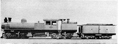
Builder’s picture of CGR Kitson-Meyer no. 800, with works number 4197 on the cab plate | |||||||||||||||||||||||||||||||||||||||||||||||||||||||||||||||||||||||||||||||||||||||||||||
| |||||||||||||||||||||||||||||||||||||||||||||||||||||||||||||||||||||||||||||||||||||||||||||
| |||||||||||||||||||||||||||||||||||||||||||||||||||||||||||||||||||||||||||||||||||||||||||||
| |||||||||||||||||||||||||||||||||||||||||||||||||||||||||||||||||||||||||||||||||||||||||||||
| |||||||||||||||||||||||||||||||||||||||||||||||||||||||||||||||||||||||||||||||||||||||||||||
The Cape Government Railways Kitson-Meyer 0-6-0+0-6-0 of 1903 was a South African steam locomotive from the pre-Union era in the Cape of Good Hope.
In 1903, the Cape Government Railways placed a single experimental 0-6-0+0-6-0 Kitson-Meyer articulated steam locomotive in service on its Eastern System, working out of East London. The Kitson-Meyer was found to be a poor steamer and it was staged out of service by 1908, and scrapped in 1912.[1][2]
Manufacturer
In 1903, English locomotive builders Kitson and Company proposed that the Cape Government Railways (CGR), the Beira and Mashonaland Railway (B&MR) and the Central South African Railways (CSAR) try their new 0-6-0+0-6-0 Kitson-Meyer articulated steam locomotive, of which the full weight of the engine would be available for adhesion.[1][2]
Since the severe gradients and curves on the mainline out of East London had been a major challenge to locomotive power ever since the line was constructed, Cape Government Railways (CGR) Locomotive Superintendent H.M. Beatty made use of the opportunity to experiment with this locomotive. One locomotive was delivered to the CGR in 1903 and numbered 800. Two more of these locomotives went to the B&MR in that same year, numbered 51 and 52, and one to the CSAR in 1904, numbered 1000.[1][2][3]
Description
The Kitson-Meyer locomotive consisted of two sets of coupled driving wheels under one frame, with both power units free to swivel in relation to the frame. Unlike the usual practice on articulated steam locomotives, where the engine units would be mounted in opposing orientations, those of the Kitson-Meyer were both mounted back-to-front, with the driving wheels forward of the cylinders. The rear engine unit discharged its exhaust steam up a chimney which was mounted in the coal bunker to the rear of the cab, while the front engine unit discharged in the usual manner, up the chimney mounted on the smokebox in front of the boiler.[2]
Meyer locomotive
The Kitson-Meyer was a development of the Meyer locomotive. On a Meyer locomotive, the two engine units were mounted close together, usually with the cylinder ends of the engine units facing each other at the centre of the locomotive. One disadvantage of this design was that the rear engine unit's cylinders were directly beneath the firebox, thereby limiting it in size.[4]
Kitson-Meyer locomotive
On the Kitson-Meyer locomotive, on the other hand, the rear engine unit was located further towards the rear, and reversed. This allowed the firebox to be between the two engine units, as would later be the practice on a Garratt locomotive, thereby making a much larger firebox possible. This also increased the length of the locomotive, making it possible to utilise the additional length behind the cab for a coal and water bunker. The auxiliary chimney at the rear avoided the need to run an exhaust steam pipe along the full length of the locomotive to the smokebox at the front end.[4]
Characteristics
Owing to the bad watering conditions prevailing in Southern Africa, the potential benefit of having the full weight of the engine available for adhesion was partially lost, since it was found necessary to attach a tender to the locomotive. This arrangement materially detracted from the hauling capacity of this type of locomotive and proved to be a serious handicap.[3]
The Kitson-Meyer locomotives which were delivered to the three Southern African railways, had Walschaerts valve gear and Belpaire fireboxes. The engines carried no water, but had a coal bunker to the rear of the cab, with a capacity of 7 long tons (7.1 tonnes). All the engine's water was carried in the tender, which had a capacity of 3,000 imperial gallons (14,000 litres) as well as an additional coal capacity of 6 long tons (6.1 tonnes).[2]
The boiler and bunker of the engine were supported by a pair of braced girders which, in turn, rested upon the two power bogies, each of which had six coupled wheels. The engine units carried the load on pivots, which were positioned as close as possible to the centres of their wheelbases. Rolling was checked by plates, concentric with each pivot centre, while pitching was checked by a slide at the end of each engine unit.[3]
The reversing and hand brake gear were provided with universal joints. The steam and exhaust pipes had ball-and-socket joints, with the centre of the ball coinciding with that of the spherical pivot casting. The exhaust of the inner cylinders, on the front power unit, passed to the smokebox via a similar ball-and-socket joint, installed close to the universal joint. The exhaust of the rear power unit's cylinders escaped through the auxiliary chimney in the coal bunker.[3]
Performance and modifications
All three railways found their Kitson-Meyers to be poor steamers and, as built, none of these locomotives had a long service life. The CGR found that, while the Kitson-Meyer could handle a one-third heavier load than a Class 8 locomotive, the boiler could not supply sufficient steam for the four cylinders on longer runs. The CGR's modifications to the tender, to increase its water capacity from 3,000 to 4,000 imperial gallons (14,000 to 18,000 litres) by decreasing the coal capacity, did not prove to be a solution.[1]
Part of the problem could probably be ascribed to the fact that the exhaust steam from the rear power unit contributed nothing to the smokebox draught, the same phenomenon which would, half a century later, necessitate the installation of induced draught equipment on South Africa’s Class 25 condensing locomotives.[5]
Service
The CGR’s Kitson-Meyer locomotive was placed in service on the Cape Eastern System, working out of East London. By 1908, however, it was standing staged out of service and remained so, until it was withdrawn from service in 1911 and scrapped in 1912. It therefore did not come onto the South African Railways roster during the 1912 renumbering and reclassification scheme. The two B&MR Kitson-Meyer locomotives were also found to be poor performers and were also withdrawn and scrapped in 1912, but the CSAR locomotive survived longer, after some modifications to the cylinders which improved its steaming ability.[1][2]
References
- 1 2 3 4 5 Holland, D.F. (1971). Steam Locomotives of the South African Railways, Volume 1: 1859-1910 (1st ed.). Newton Abbott, Devon: David & Charles. pp. 69–70, 130–132. ISBN 978-0-7153-5382-0.
- 1 2 3 4 5 6 Paxton, Leith; Bourne, David (1985). Locomotives of the South African Railways (1st ed.). Cape Town: Struik. p. 84. ISBN 0869772112.
- 1 2 3 4 Espitalier, T.J.; Day, W.A.J. (1944). The Locomotive in South Africa - A Brief History of Railway Development. Chapter II - The Cape Government Railways (Continued). South African Railways and Harbours Magazine, March 1944. pp. 169-173.
- 1 2 Binns, Donald (2003). Kitson Meyer Articulated Locomotives. Trackside Publications, Skipton, UK. ISBN 0-907941-37-0
- ↑ Holland, D.F. (1972). Steam Locomotives of the South African Railways, Volume 2: 1910-1955 (1st ed.). Newton Abbott, Devon: David & Charles. pp. 110, 140. ISBN 978-0-7153-5427-8.
| Wikimedia Commons has media related to CGR Kitson-Meyer 0-6-0+0-6-0. |