Buffers and chain coupler


Buffers and chain coupler (also called buffers and screw, screw coupler, or English coupler; in EU standards, it's two devices: buffers[1] and draw gear and screw coupling[2]) is the standard train coupling system used in Europe, outside the former Soviet Union. It is also occasionally used outside Europe.
The vehicles are coupled by hand using a hook and links with a turnbuckle that draws the vehicles together. In Britain, this is called a screw coupling. Vehicles have buffers, one at each corner on the ends, which are pulled together and compressed by the coupling device. This arrangement limits the slack in trains and lessens shunting shocks. By contrast, the semi-automatic Janney coupler usually requires comparatively jarring encounters in order to engage the coupling fully. The earliest buffers were fixed extensions of the wagon frames, but later spring buffers were introduced.
Inefficient and slow, the European system is also relatively unsafe because — like the link-and-pin coupling used in North America (and especially the United States) before the end of the 19th century, when the Janney coupler began universally replacing it there — the European system requires manual coupling between vehicles, exposing workers to the risk of being crushed. However, there is no need for the worker to go between vehicles while they are moving, which is one improvement over the original link-and-pin types.
Characteristics

The standard type of coupling on railways following the British tradition is the buffer and chain coupling used on the pioneering Planet class locomotive of the Liverpool and Manchester Railway of 1830. These couplings followed earlier tramway practice but were made more regular.
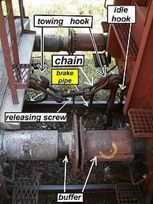
This coupling is still the standard in European countries (except the former Soviet Union, where the SA-3 automatic coupler is used). Coupling is done by a worker who must climb between the cars. First he winds the turnbuckle to the loose position, and then he can hang the chain on the hook. After hanging the chain on the towing hook the turnbuckle handle is stowed on the idle hook to prevent damage to itself, the vehicle, or the brake pipes. Only shunting is permitted with a dangling chain. Disconnected brake pipes must be stowed on dummy connectors, to allow proper operation of the brakes. (The picture shows two coupled cars, with a single brake pipe.)
The hooks and chain hold the carriages together, while the buffers keep the carriages from banging into each other so that no damage is caused. The buffers can be "dumb" or spring-loaded. That means there are no run-in forces on the coupler. The other benefit compared with automatic couplers is that its lesser slack causes smaller forces on curves; there is a lower probability of a broken coupler in a curve than with automatic couplers. The disadvantage is the smaller mass of the freight that can be hauled by hook and chain couplers (maximum 4,000 t or 3,937 long tons or 4,409 short tons).
Early rolling stock was often fitted with a pair of auxiliary chains as a backup if the main coupling failed. This made sense before the fitting of continuous fail-safe braking systems.
On railways where rolling stock always pointed the same way, the chain might be mounted at one end only, as a small cost and weight saving measure.
On German and Scandinavian railways, the left buffer is flatter than the right one, which is slightly more rounded. This provides better contact between the buffers than would be the case if both buffers were slightly rounded.
Variants
Three-link couplings
A peculiarly British institution was the "loose-coupled" freight train. This used three-link chain couplings with no means of drawing the wagons together: since such trains were not fitted with an automatic through-train braking system there were no pipes to connect between the vehicles. The couplings in the train were kept taut by the last vehicle of the train being a heavily ballasted guard's van with its brakes set slightly on. This helped prevent snapped couplings. Such trains travelled at low speeds and were phased out in the 1970s.[3]
An improvement on this is the "Instanter" coupling, in which the middle link of a three link chain is specially shaped so that when lying "prone" it provides enough slack to make coupling possible, but when this middle link is rotated 90 degrees the length of the chain is effectively shortened, reducing the amount of slack without the need to wind a screw. The closeness of the coupling allows the use of inter-vehicle pipes for train brakes. It also has the advantage that it can be operated entirely from the side of the wagons using a shunter's pole and is therefore safer when shunting work is under way. These couplings have been superseded by buck-eye couplers in UK freight trains today.
Center-buffer-and-chain(s)
On some narrow-gauge lines in Europe and on the Paris Metro a simplified version is used, consisting of a single central buffer with a chain underneath. Sometimes there are two chains, one on each side of the coupler. The chain usually contains a screw-adjustable link to allow close coupling. These variants are also used elsewhere. On sharp curves, a single centre buffer is less likely to be subject to buffer-locking.
Buffer-and-chain on the narrow gauge
Buffer-and-chain couplers do not allow very sharp curves, and there is a buffer-locking problem if pushing the limit. Because of that – and Carl Pihl's successful promotion of the single-buffer Norwegian coupler that he designed to overcome this – conventional buffers-and-chain coupling is rarely employed on narrow-gauge systems: notable exceptions being the railway networks of Senegal/Mali, Tunisia and Côte d'Ivoire/Burkina Faso in Africa, and Queensland and Tasmania in Australia. Narrow gauge railways are often isolated from other railways, so standardization is not so important.
Problems with buffers and chain
Maximum load
The buffers and chain coupling system has a maximum load much less than that of the Janney coupler. They allow around 3,000-4,000 (metric) tonnes total train weight depending on the how they are constructed. The Janney coupler sometimes is built for 32,000 tonnes.
Buffer-locking

On sharp reverse curves, the buffers can get buffer-locked by slipping over – and onto the back of – an adjacent buffer. Although careful track design makes this occurrence rare, an accident at a Swiss station in the 1980s was caused by buffer-locked wagons. Buffer-lock could be caused on the very sharp switches by the older, rounded buffers. The newer buffers are rectangular and they are wider than they are tall. They are not as flat, so they rarely cause buffer-locking. Buffers and chain coupler allow curves to have around 150 m radius, but so sharp S-curves are not allowed. If it weren't for the couplers, much sharper corners could be allowed, on the condition the train is not so long. Tramways exist with 20 m (66 ft), or less. curve radius, with center couplers.
Variation with gauge
The width between the buffers tends to increase as the gauge increases or decrease as the gauge decreases, so that if wagons are changed from one gauge to another, the buffers will no longer match. This occurs because the buffers are originally extensions of the frames, which are spaced according to the gauge. Conversely, as gauge gets smaller, the distance between the buffers reduces also. The height of the buffers is usually lower on narrow gauge railways, corresponding to the generally lower height of the rolling stock. In short, when rebuilding wagons from one gauge to another, more work is needed.
However, in the case of Iberian broad gauge railways, the buffer's height and spacing is the same as for the standard gauge railways in Europe including Great Britain in order to allow though running of rolling stock by the use of bogie exchange.
Dimensions
Buffers and chain couplers tend to have the two buffers spaced according to the gauge, but especially in Europe this is modified to the standard gauge value to allow interrunning by means of bogie exchange.
Dimensions showing variation of spacing by gauge.
| Name | Gauge | Height | Separation | Region |
|---|---|---|---|---|
| Standard gauge | 1435 mm | 1,054 mm (41.5 in) | 1,727 mm (68.0 in)[4] | Great Britain, European mainland |
| Metre gauge | 1000 mm | 0,756 mm (29.8 in) | 1,248 mm (49.1 in) | Senegal/Mali Jane's World Railways 1969-1970 edition |
| Broad gauge | 1520 mm | 1,063 mm (41.9 in) | 1,727 mm (68.0 in) | Dual-gauge (Europe/Russia) sleeping car[5] |
| Broad gauge | 1676 mm | 1,050 mm (41.3 in) | 1,720 mm (68 in) | Spain and Portugal |
| Broad gauge | 1676 mm | 1,067 mm (42.0 in) | 1,955 mm (77 in) | India, Pakistan and Sri Lanka |
Gallery
 Traditional buffer-and-chain coupler 1435mm gauge
 Buffer-and-chain coupler 1000mm gauge in Ivory Coast * Burkina Faso
 Switzerland Rhätische Bahn (1,000 mm (3 ft 3 3⁄8 in)) "Centre-buffer-&-chains" coupler, called Balancierhebelkupplung
See also
References
- ↑ EN 15551:2009+A1:2010 Railway applications – Railway rolling stock – Buffers
- ↑ EN 15566-2009+A1:2010 Railway applications – Railway rolling stock – Draw gear and screw coupling
- ↑ http://www.wsr.org.uk/couplings.htm
- ↑ Steam Spirit, Vol 1, p 129
- ↑ Railway Gazette International Sept 2012, p 108
External links
-
 Media related to Screw coupling at Wikimedia Commons
 - Buffer and chain