Broadcast television systems
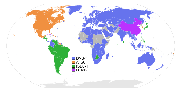
Broadcast television systems are encoding or formatting standards for the transmission and reception of terrestrial television signals. There were three main analog television systems in use around the world until late 2010s (expected): NTSC, PAL, and SECAM. Now in digital television (DTV), there are four main systems in use around the world: ATSC, DVB, ISDB and DTMB.
Analog television systems
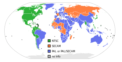
All but one analog television system began as black-and-white systems. Each country, faced with local political, technical, and economic issues, adopted a color television system which was grafted onto an existing monochrome system, using gaps in the video spectrum (explained below) to allow color transmission information to fit in the existing channels allotted. The grafting of the color transmission standards onto existing monochrome systems permitted existing monochrome television receivers predating the changeover to color television to continue to be operated as monochrome television. Because of this compatibility requirement, color standards added a second signal to the basic monochrome signal, which carries the color information. The color information is called chrominance with the symbol C, while the black and white information is called the luminance with the symbol Y. Monochrome television receivers only display the luminance, while color receivers process both signals. Though in theory any monochrome system could be adopted to a color system, in practice some of the original monochrome systems proved impractical to adapt to color and were abandoned when the switch to color broadcasting was made. All countries used one of three color systems: NTSC, PAL, or SECAM.
Frames
Ignoring color, all television systems work in essentially the same manner. The monochrome image seen by a camera (later, the luminance component of a color image) is divided into horizontal scan lines, some number of which make up a single image or frame. A monochrome image is theoretically continuous, and thus unlimited in horizontal resolution, but to make television practical, a limit had to be placed on the bandwidth of the television signal, which puts an ultimate limit on the horizontal resolution possible. When color was introduced, this necessity of limit became fixed. All analog television systems are interlaced: alternate rows of the frame are transmitted in sequence, followed by the remaining rows in their sequence. Each half of the frame is called a video field, and the rate at which fields are transmitted is one of the fundamental parameters of a video system. It is related to the utility frequency at which the electricity distribution system operates, to avoid flicker resulting from the beat between the television screen deflection system and nearby mains generated magnetic fields. All digital, or "fixed pixel," displays have progressive scanning and must deinterlace an interlaced source. Use of inexpensive deinterlacing hardware is a typical difference between lower- vs. higher-priced flat panel displays (Plasma display, LCD, etc.).
All films and other filmed material shot at 24 frames per second must be transferred to video frame rates using a telecine in order to prevent severe motion jitter effects. Typically, for 25 frame/s formats (European among other countries with 50 Hz mains supply), the content is PAL speedup, while a technique known as "3:2 pulldown" is used for 30 frame/s formats (North America among other countries with 60 Hz mains supply) to match the film frame rate to the video frame rate without speeding up the play back.
Viewing technology
Analog television signal standards are designed to be displayed on a cathode ray tube (CRT), and so the physics of these devices necessarily controls the format of the video signal. The image on a CRT is painted by a moving beam of electrons which hits a phosphor coating on the front of the tube. This electron beam is steered by a magnetic field generated by powerful electromagnets close to the source of the electron beam.
In order to reorient this magnetic steering mechanism, a certain amount of time is required due to the inductance of the magnets; the greater the change, the greater the time it takes for the electron beam to settle in the new spot.
For this reason, it is necessary to shut off the electron beam (corresponding to a video signal of zero luminance) during the time it takes to reorient the beam from the end of one line to the beginning of the next (horizontal retrace) and from the bottom of the screen to the top (vertical retrace or vertical blanking interval). The horizontal retrace is accounted for in the time allotted to each scan line, but the vertical retrace is accounted for as phantom lines which are never displayed but which are included in the number of lines per frame defined for each video system. Since the electron beam must be turned off in any case, the result is gaps in the television signal, which can be used to transmit other information, such as test signals or color identification signals.
The temporal gaps translate into a comb-like frequency spectrum for the signal, where the teeth are spaced at line frequency and concentrate most of the energy; the space between the teeth can be used to insert a color subcarrier.
Hidden signaling
Broadcasters later developed mechanisms to transmit digital information on the phantom lines, used mostly for teletext and closed captioning:
- PALplus uses a hidden signaling scheme to indicate if it exists, and if so what operational mode it is in.
- NTSC has been modified by the Advanced Television Systems Committee to support an anti-ghosting signal that is inserted on a non-visible scan line.
- Teletext uses hidden signaling to transmit information pages.
- NTSC Closed Captioning signaling uses signaling that is nearly identical to teletext signaling.
- Widescreen All 625 line systems incorporate pulses on line 23 that flag to the display that a 16:9 widescreen image is being broadcast, though this option was not used on later analog transmissions.
Overscan
Television images are unique in that they must incorporate regions of the picture with reasonable-quality content, that will never be seen by some viewers.
Interlacing
In a purely analog system, field order is merely a matter of convention. For digitally recorded material it becomes necessary to rearrange the field order when conversion takes place from one standard to another.
Image polarity
Another parameter of analog television systems, minor by comparison, is the choice of whether vision modulation is positive or negative. Some of the earliest electronic television systems such as the British 405-line (system A) used positive modulation. It was also used in the two Belgian systems (system C, 625 lines, and System F, 819 lines) and the two French systems (system E, 819 lines, and system L, 625 lines). In positive modulation systems, as in the earlier white facsimile transmission standard, the maximum luminance value is represented by the maximum carrier power; in negative modulation, the maximum luminance value is represented by zero carrier power. All newer analog video systems use negative modulation with the exception of the French System L.
Impulsive noise, especially from older automotive ignition systems, caused white spots to appear on the screens of television receivers using positive modulation but they could use simple synchronization circuits. Impulsive noise in negative modulation systems appears as dark spots that are less visible, but picture synchronization was seriously degraded when using simple synchronization. The synchronization problem was overcome with the invention of phase-locked synchronization circuits. When these first appeared in Britain in the early 1950s one name used to describe them was "flywheel synchronisation."
Older televisions for positive modulation systems were sometimes equipped with a peak video signal inverter that would turn the white interference spots dark. This was usually user-adjustable with a control on the rear of the television labeled "White Spot Limiter" in Britain or "Antiparasite" in France. If adjusted incorrectly it would turn bright white picture content dark. Most of the positive modulation television systems ceased operation by the mid-1980s. The French System L continued on up to the transition to digital broadcasting. Positive modulation was one of several unique technical features that originally protected the French electronics and broadcasting industry from foreign competition and rendered French TV sets incapable of receiving broadcasts from neighboring countries.
Another advantage of negative modulation is that, since the synchronizing pulses represent maximum carrier power, it is relatively easy to arrange the receiver automatic gain control to only operate during sync pulses and thus get a constant amplitude video signal to drive the rest of the TV set. This was not possible for many years with positive modulation as the peak carrier power varied depending on picture content. Modern digital processing circuits have achieved a similar effect but using the front porch of the video signal.
Modulation
Given all of these parameters, the result is a mostly-continuous analog signal which can be modulated onto a radio-frequency carrier and transmitted through an antenna. All analog television systems use vestigial sideband modulation, a form of amplitude modulation in which one sideband is partially removed. This reduces the bandwidth of the transmitted signal, enabling narrower channels to be used.
Audio
In analog television, the analog audio portion of a broadcast is invariably modulated separately from the video. Most commonly, the audio and video are combined at the transmitter before being presented to the antenna, but separate aural and visual antennas can be used. In all cases where negative video is used, FM is used for the standard monaural audio; systems with positive video use AM sound and intercarrier receiver technology cannot be incorporated. Stereo, or more generally multi-channel, audio is encoded using a number of schemes which (except in the French systems) are independent of the video system. The principal systems are NICAM, which uses a digital audio encoding; double-FM (known under a variety of names, notably Zweikanalton, A2 Stereo, West German Stereo, German Stereo or IGR Stereo), in which case each audio channel is separately modulated in FM and added to the broadcast signal; and BTSC (also known as MTS), which multiplexes additional audio channels into the FM audio carrier. All three systems are compatible with monaural FM audio, but only NICAM may be used with the French AM audio systems.
Evolution
For historical reasons, some countries use a different video system on UHF than they do on the VHF bands. In a few countries, most notably the United Kingdom, television broadcasting on VHF has been entirely shut down. Note that the British 405-line system A, unlike all the other systems, suppressed the upper sideband rather than the lower—befitting its status as the oldest operating television system to survive into the color era (although was never officially broadcast with color encoding). System A was tested with all three color systems, and production equipment was designed and ready to be built; System A might have survived, as NTSC-A, had the British government not decided to harmonize with the rest of Europe on a 625-line video standard, implemented in Britain as PAL-I on UHF only.
The French 819 line system E was a post-war effort to advance France's standing in television technology. Its 819-lines were almost high definition even by today's standards. Like the British system A, it was VHF only and remained black & white until its shutdown in 1984 in France and 1985 in Monaco. It was tested with SECAM in the early stages, but later the decision was made to adopt color in 625-lines. Thus France adopted system L on UHF only and abandoned system E.
In many parts of the world, analog television broadcasting has been shut down completely, or in process of shutdown; see Digital television transition for a timeline of the analog shutdown.
List of analog television systems
Pre–World War II systems
A number of experimental and broadcast pre WW2 systems were tested. The first ones were mechanically based and of very low resolution, sometimes with no sound. Later TV systems were electronic.
- The UK 405 line system was the first to have an allocated ITU System Letter Designation.
ITU standards
On an international conference in Stockholm in 1961, the International Telecommunication Union designated standards for broadcast television systems.[1] Each standard is designated a letter (A-M); in combination with a color system (NTSC, PAL, SECAM), this completely specifies all of the monaural analog television systems in the world (for example, PAL-B, NTSC-M, etc.).
The following table gives the principal characteristics of each standard. Defunct TV systems are shown in grey text, previous ones never designated by ITU are not yet shown. Except for lines and frame rates, other units are megahertz (MHz).
- Also see: television channel frequencies
| Standard | Introduced | Lines | Frame rate | Channel bandwidth | Video bandwidth (MHz) | Vision sound carrier separation (MHz) | Vestigial sideband (MHz) | Vision modulation | Sound modulation | Frequency of chrominance subcarrier (MHz) | Vision/sound power ratio | Usual color |
|---|---|---|---|---|---|---|---|---|---|---|---|---|
| A | 1936 | 405 | 25 | 5 | 3 | −3.5 | 0.75 | pos. | AM | 4:1 | none | |
| B | 1950 | 625 | 25 | 7 | 5 | +5.5 | 0.75 | neg. | FM | PAL/SECAM | ||
| C | 1953 | 625 | 25 | 7 | 5 | +5.5 | 0.75 | pos. | AM | none | ||
| D | 1948 | 625 | 25 | 8 | 6 | +6.5 | 0.75 | neg. | FM | SECAM/PAL | ||
| E | 1949 | 819 | 25 | 14 | 10 | ±11.15 | 2.00 | pos. | AM | none | ||
| F | 819 | 25 | 7 | 5 | +5.5 | 0.75 | pos. | AM | none | |||
| G | 625 | 25 | 8 | 5 | +5.5 | 0.75 | neg. | FM | 4.43 | 5:1 | PAL/SECAM | |
| H | 625 | 25 | 8 | 5 | +5.5 | 1.25 | neg. | FM | 4.43 | 5:1 | PAL | |
| I | 1962 | 625 | 25 | 8 | 5.5 | +5.9996 | 1.25 | neg. | FM | 4.43 | 5:1 | PAL |
| J | 1953 | 525 | 30 | 6 | 4.2 | +4.5 | 0.75 | neg. | FM | 3.58 | NTSC | |
| K | 625 | 25 | 8 | 6 | +6.5 | 0.75 | neg. | FM | 4.43 | 5:1 | SECAM/PAL | |
| K' | 625 | 25 | 8 | 6 | +6.5 | 1.25 | neg. | FM | SECAM | |||
| L | 1970s | 625 | 25 | 8 | 6 | -6.5 | 1.25 | pos. | AM | 4.43 | 8:1 | SECAM |
| M | 1941 | 525 | 30 | 6 | 4.2 | +4.5 | 0.75 | neg. | FM | 3.58 | NTSC | |
| N | 1951 | 625 | 25 | 6 | 4.2 | +4.5 | 0.75 | neg. | FM | PAL |
Notes by system
- A
- Early United Kingdom and Ireland VHF system (B&W only). First electronic TV system, introduced in 1936. Vestigal sideband filtering introduced in 1949. Discontinued on 23 November 1982 in Ireland and on 2 January 1985 in the UK.
- B
- VHF only in most countries (combined with system G and H on UHF); VHF and UHF in Australia Originally known as the Gerber standard # .
- C
- Early VHF system; used only in Belgium, Italy, the Netherlands and Luxembourg, as a compromise between Systems B and L. Discontinued in 1977.
- D
- Used on VHF only in most countries (combined with system K on UHF). Used in the People's Republic of China (PAL-D) on both VHF and UHF.
- E
- Early French VHF system (B&W only); very good (near HDTV) picture quality but uneconomical use of bandwidth. Sound carrier separation +11.15 MHz on odd numbered channels, -11.15 MHz on even numbered channels. Discontinued in 1984 (France) and 1985 (Monaco).
- F
- Early VHF system used only in Belgium, Italy, the Netherlands and Luxembourg; allowed French 819-line television programming to be broadcast on the 7 MHz VHF channels used in those countries, at a substantial cost in horizontal resolution. Discontinued in 1969.
- G
- UHF only; used in countries with System B on VHF, except Australia.
- H
- UHF only; used only in Belgium, Luxembourg, Netherlands and Former Yugoslavia. Similar to System G with an 1.25 MHz vestigal sideband.
- I
- Used in the UK, Ireland, Southern Africa, Macau, Hong Kong and Falkland Islands.
- J
- Used in Japan (see system M below). Identical to system M except that a different black level of 0 IRE is used instead of 7.5 IRE. Although the ITU specified a frame rate of 30 fields, 29.97 was adopted with the introduction of NTSC color to minimize visual artifacts. Discontinued in 2012, when Japan transitioned to digital.
- K
- UHF only; used in countries with system D on VHF, and identical to it in most respects.
- K'
- Used only in French overseas departments and territories.
- L
- Used only in France. On VHF Band 1 only, the audio is at −6.5 MHz. Discontinued in 2011, when France transitioned to digital. It was the last system to use positive video modulation and AM sound.
- M
- Used in most of the Americas and Caribbean, Myanmar, South Korea, Taiwan, Philippines (all NTSC-M), Brazil (PAL-M) and Laos (SECAM-M). Although the ITU specified a frame rate of 30 fields, 29.97 was adopted with the introduction of NTSC color to minimize visual artifacts. PAL-M, unaffected by color encoding, continues to use a frame rate of 30.
- N
- Originally developed for Japan but not taken up. Adopted by Argentina, Paraguay and Uruguay (since 1980) (all PAL-N), and used briefly in Brazil and Venezuela. Allows 625-line, 50-frame/s video to be broadcast in a 6-MHz channel, at some cost in horizontal resolution.
Digital television systems
The situation with worldwide digital television is much simpler by comparison. Most digital television systems are based on the MPEG transport stream standard, and use the H.262/MPEG-2 Part 2 video codec. They differ significantly in the details of how the transport stream is converted into a broadcast signal, in the video format prior to encoding (or alternatively, after decoding), and in the audio format. This has not prevented the creation of an international standard that includes both major systems, even though they are incompatible in almost every respect.
The two principal digital broadcasting systems are ATSC standards, developed by the Advanced Television Systems Committee and adopted as a standard in most of North America, and DVB-T, the Digital Video Broadcast – Terrestrial system used in most of the rest of the world. DVB-T was designed for format compatibility with existing direct broadcast satellite services in Europe (which use the DVB-S standard, and also sees some use in direct-to-home satellite dish providers in North America), and there is also a DVB-C version for cable television. While the ATSC standard also includes support for satellite and cable television systems, operators of those systems have chosen other technologies (principally DVB-S or proprietary systems for satellite and 256QAM replacing VSB for cable). Japan uses a third system, closely related to DVB-T, called ISDB-T, which is compatible with Brazil's SBTVD. The People's Republic of China has developed a fourth system, named DMB-T/H.
ATSC
The terrestrial ATSC system (unofficially ATSC-T) uses a proprietary Zenith-developed modulation called 8-VSB; as the name implies, it is a vestigial sideband technique. Essentially, analog VSB is to regular amplitude modulation as 8VSB is to eight-way quadrature amplitude modulation. This system was chosen specifically to provide for maximum spectral compatibility between existing analog TV and new digital stations in the United States' already-crowded television allocations system, although it is inferior to the other digital systems in dealing with multipath interference; however, it is better at dealing with impulse noise which is especially present on the VHF bands that other countries have discontinued from TV use, but are still used in the U.S. There is also no hierarchical modulation. After demodulation and error-correction, the 8-VSB modulation supports a digital data stream of about 19.39 Mbit/s, enough for one high-definition video stream or several standard-definition services. See Digital subchannel#Technical considerations for more information.
On cable, ATSC usually uses 256QAM, although some use 16VSB. Both of these double the throughput to 38.78 Mbit/s within the same 6 MHz bandwidth. ATSC is also used over satellite. While these are logically called ATSC-C and ATSC-S, these terms were never officially defined.
DTMB
DTMB is the digital television broadcasting standard of the People's Republic of China, Hong Kong and Macau. This is a fusion system, which is a compromise of different competing proposing standards from different Chinese Universities, which incorporates elements from DMB-T, ADTB-T and TiMi 3.
DVB
DVB-T uses coded orthogonal frequency division multiplexing (COFDM), which uses as many as 8000 independent carriers, each transmitting data at a comparatively low rate. This system was designed to provide superior immunity from multipath interference, and has a choice of system variants which allow data rates from 4 MBit/s up to 24 MBit/s. One US broadcaster, Sinclair Broadcasting, petitioned the Federal Communications Commission to permit the use of COFDM instead of 8-VSB, on the theory that this would improve prospects for digital TV reception by households without outside antennas (a majority in the US), but this request was denied. (However, one US digital station, WNYE-DT in New York, was temporarily converted to COFDM modulation on an emergency basis for datacasting information to emergency services personnel in lower Manhattan in the aftermath of the September 11 terrorist attacks).
DVB-S is the original Digital Video Broadcasting forward error coding and modulation standard for satellite television and dates back to 1995. It is used via satellites serving every continent of the world, including North America. DVB-S is used in both MCPC and SCPC modes for broadcast network feeds, as well as for direct broadcast satellite services like Sky and Freesat in the British Isles, Sky Deutschland and HD+ in Germany and Austria, TNT SAT/FRANSAT and CanalSat in France, Dish Network in the US, and Bell TV in Canada. The MPEG transport stream delivered by DVB-S is mandated as MPEG-2.
DVB-C stands for Digital Video Broadcasting - Cable and it is the DVB European consortium standard for the broadcast transmission of digital television over cable. This system transmits an MPEG-2 family digital audio/video stream, using a QAM modulation with channel coding.
ISDB
ISDB is very similar to DVB, however it is broken into 13 subchannels. Twelve are used for TV, while the last serves either as a guard band, or for the 1seg (ISDB-H) service. Like the other DTV systems, the ISDB types differ mainly in the modulations used, due to the requirements of different frequency bands. The 12 GHz band ISDB-S uses PSK modulation, 2.6 GHz band digital sound broadcasting uses CDM and ISDB-T (in VHF and/or UHF band) uses COFDM with PSK/QAM. It was developed in Japan with MPEG-2, and is now used in Brazil with MPEG-4. Unlike other digital broadcast systems, ISDB includes digital rights management to restrict recording of programming.
Comparison of digital terrestrial television systems
| System | Digital Modulation | Lines | Frame rate | Data rate | Hierarchical Mod. | Ch. B/W (MHz) | Video B/W | Audio offset | VSB | Video Coding | Audio Coding | Interactive TV | Digital subchannels | Single-Frequency Network | Predecessor format(s) | Mobile? |
|---|---|---|---|---|---|---|---|---|---|---|---|---|---|---|---|---|
| ATSC | 8VSB, A-VSB and E-VSB in the works | 1080 | up to 60p | 19.39 MB/s | No | 6 | 4.25? digital carrier at 1.31 | ? | 8VSB | H.262 | Dolby Digital, AC3, MPEG-1 Layer II | DSM-CC MHEG-5, PSIP | Yes | Partial | NTSC | Not yet, ATSC-M/H in the works |
| DVB-T | COFDM (QPSK, 16/64QAM) | 1080 | up to 50p | Up to 31.668 MB/s | Yes | 5, 6, 7, or 8 | ? | ? | ? | H.262, H.264 | MPEG-1 Layer II, HE-AAC | DSM-CC MHEG-5, DVB-SI | Yes | Yes | PAL, SECAM | Yes (DVB-H) |
| DVB-T2 | COFDM (QPSK, 16/64/256QAM) | 1080 | up to 50p | Up to 50.34 Mbit/s | Yes | 1.7, 5, 6, 7, 8, or 10 | ? | ? | ? | H.264, H.262 | MPEG-1 Layer II, HE-AAC | DSM-CC MHEG-5, DVB-SI | Yes | Yes | DVB-T | DVB-NGH |
| DMB-T/H | TDS-OFDM | 1080 | up to 50p | ? | ? | 6, 7, or 8 | ? | ? | ? | MPEG-2, H.264/MPEG-4 AVC, AVS | MPEG-1 Audio Layer II, AC3 | Yes | ? | Yes | PAL | Yes |
| ISDB-T | 16/64QAM-OFDM (QPSK-OFDM/ DQPSK-OFDM) | 1080? | up to 60p | 19.39 MB/s | Yes | 6 (5.572 + 428 kHz guard band) | ? | ? | ? | H.262/ H.264 (1seg) | AAC | No | Yes | Yes | NTSC | Yes, ISDB-Tmm/1seg |
| ISDB-Tb (SBTVD) | BST-OFDM | 1080? | ? | ? | Yes | 6 | ? | ? | ? | H.264 | HE-AAC | Yes, Ginga | Yes | Yes | PAL-M, PAL-N, NTSC | Yes, 1seg |
| MediaFLO | OFDM (QPSK/16QAM) | ? | ? | ? | ? | 5.55 | ? | ? | ? | ? | ? | Yes | ? | ? | NTSC () | Yes |
| T-DMB | OFDM-DQPSK | ? | ? | ? | ? | ? | ? | ? | ? | H.262/ H.264 | HE-AAC | ? | ? | ? | NTSC | Yes |
Line count
As interlaced systems require accurate positioning of scanning lines, it is important to make sure that the horizontal and vertical timebase are in a precise ratio. This is accomplished by passing the one through a series of electronic divider circuits to produce the other. Each division is by a prime number.
Therefore, there has to be a straightforward mathematical relationship between the line and field frequencies, the latter being derived by dividing down from the former. Technology constraints of the 1930s meant that this division process could only be done using small integers, preferably no greater than 7, for good stability. The number of lines was odd because of 2:1 interlace. The 405 line system used a vertical frequency of 50 Hz (Standard AC mains supply frequency in Britain) and a horizontal one of 10,125 Hz (50 × 405 ÷ 2)
- 2 × 3 × 3 × 5 gives 90 lines (non interlaced)
- 2 × 2 × 2 × 2 × 2 × 3 gives 96 lines (non interlaced)
- 2 × 2 × 3 × 3 × 5 gives 180 lines (non interlaced) (used in Germany in mid-1930s before switch to 441-line system)
- 2 × 2 × 2 × 2 × 3 × 5 gives 240 lines (used for the experimental Baird transmissions in Britain [See Note 1])
- 3 × 3 × 3 × 3 × 3 gives 243 lines
- 7 × 7 × 7 gives 343 lines (early North American system also used in Poland and in Soviet Union before WW2)
- 3 × 5 × 5 × 5 gives 375 lines
- 3 × 3 × 3 × 3 × 5 gives 405 lines System A (used in Britain, Ireland and Hong Kong before 1985)
- 2 × 2 × 2 × 5 × 11 gives 440 lines (non interlaced)
- 3 × 3 × 7 × 7 gives 441 lines (used by RCA in North America before the 525-lines NTSC standard was adopted and widely used before WW2 in Continental Europe with different frame rates)
- 2 × 3 × 3 × 5 × 5 gives 450 lines (non interlaced)
- 5 × 7 × 13 gives 455 lines (used in France before WW2)
- 3 × 5 × 5 × 7 gives 525 lines System M (a compromise between the RCA and Philco systems. Still used today in most of the Americas and parts of Asia)
- 3 × 3 × 3 × 3 × 7 gives 567 lines (used for a while after WW2 in the Netherlands)
- 5 × 11 × 11 gives 605 lines (proposed by Philco in North America before the 525 standard was adopted)
- 5 × 5 × 5 × 5 gives 625 lines (576i) (developed independently by German and Soviet[3][4][5] engineers during the mid-late 1940s. Still used today in most parts of the world)
- 2 × 3 × 5 × 5 × 5 gives 750 lines at 50 frames (used for 720p50 [See Note 2])
- 2 × 2 × 2 × 2 × 3 × 3 × 5 gives 750 lines at 60 frames (used for 720p60 [See Note 2])
- 3 × 3 × 7 × 13 gives 819 lines (737i) (used in France in the 1950s)
- 3 × 7 × 7 × 7 gives 1029 lines (proposed but never adopted around 1948 in France)
- 3 × 3 × 5 × 5 x 5 gives 1125 lines at 25 frames (used for 1080i25 but not 1080p25 [See Note 2])
- 3 × 3 × 5 × 5 x 5 gives 1125 lines at 30 frames (used for 1080i30 but not 1080p30 [See Note 2])
- Notes
- The division of the 240-line system is academic as the scan ratio was determined entirely by the construction of the mechanical scanning system used with the cameras used with this transmission system.
- The division ratio though relevant to CRT-based systems is largely academic today because modern LCD and plasma displays are not constrained to having the scanning in precise ratios. The 1080p high definition system requires 1126-lines in a CRT display.
- The System I version of the 625 line standard originally used 582 active lines before later changing to 576 in line with other 625 line systems.
Conversion from one system to another system
Converting between different numbers of lines and different frequencies of fields/frames in video pictures is not an easy task. Perhaps the most technically challenging conversion to make is from any of the 625-line, 25-frame/s systems to system M, which has 525-lines at 29.97 frames per second. Historically this required a frame store to hold those parts of the picture not actually being output (since the scanning of any point was not time coincident). In more recent times, conversion of standards is a relatively easy task for a computer.
Aside from the line count being different, it's easy to see that generating 59.94 fields every second from a format that has only 50 fields might pose some interesting problems. Every second, an additional 10 fields must be generated seemingly from nothing. The conversion has to create new frames (from the existing input) in real time.
There are several methods used to do this, depending on the desired cost and conversion quality. The simplest possible converters simply drop every 5th line from every frame (when converting from 625 to 525) or duplicate every 4th line (when converting from 525 to 625), and then duplicate or drop some of those frames to make up the difference in frame rate. More complex systems include inter-field interpolation, adaptive interpolation, and phase correlation.
See also
- Characteristics of television systems. International Telecommunication Union, ITU-R Recommendation BT.470-2.
Transmission technology standards
- Amateur television
- Broadcast safe
- Channel (broadcasting)
- Display resolution
- Lists of television channels for lists by country and language.
- North American cable television frequencies
- Television channel frequencies
Defunct analog systems
Analog television systems
- Intercarrier method
- NTSC (525/60)
- PAL (color encoding usually used with 625/50 systems)
- PAL-M
- PAL-N
- PALplus
- SECAM
- Transposers
- TV transmitters
Analog television system audio
- BTSC
- NICAM (digital, analog pre-emphasis curve)
- Zweiton
- The defunct MUSE system had a very unusual digital audio subsystem completely unrelated to NICAM.
Digital television systems
- HDTV systems all use MPEG transport technology
- ATSC standards
- DVB-T and DVB-T2
- ISDB and ISDB-T International (SBTVD)
- DTMB used in People's Republic of China, Hong Kong and Macau.
History
References
- ↑ Final acts of the European Broadcasting Conference in the VHF and UHF bands. Stockholm, 1961.
- ↑ DVB.org, Official information taken from the DVB website
- ↑ On the beginning of broadcast in 625-lines 60 year s ago, 625 magazine (in Russian).
- ↑ M.I. Krivocheev – an engineer’s engineer, EBU's technical review.
- ↑ IN THE VANGUARD OF TELEVISION BROADCASTING
External links
- FARWAY IRFC, TV and Radio Transmission , Radio Data System Encoders , Broadcasting Technologies
- World Analog Television Standards and Waveforms by Alan Pemberton
- Analog TV Broadcast Systems by Paul Schlyter
- European Television Stations in 1932 a scan from a 1932 French magazine