Bit blit
Bit blit (also written BITBLT, BIT BLT, BitBLT, Bit BLT, Bit Blt etc., which stands for bit block transfer) is a data operation commonly used in computer graphics in which several bitmaps are combined into one using a boolean function.[1]
The operation involves at least two bitmaps, one source and destination, possibly a third that is often called the "mask" and sometimes a fourth used to create a stencil. The pixels of each are combined bitwise according to the specified raster operation (ROP) and the result is then written to the destination. The ROP is essentially a boolean formula. The most obvious ROP overwrites the destination with the source. Other ROPs may involve AND, OR, XOR, and NOT operations.[1] The Commodore Amiga's graphics chipset, for example, could combine three source bitmaps according to any of 256 boolean functions of three variables.
Modern graphics software has almost completely replaced bitwise operations with more general mathematical operations used for effects such as alpha compositing. This is because bitwise operations on color displays do not usually produce results that resemble the physical combination of lights or inks. Some software, like Windows 10, still uses XOR to draw interactive highlight rectangles; when this is done to color images, the unusual resulting colors are easily seen.
Origins
The name derives from the BitBLT routine for the Xerox Alto computer, standing for bit-boundary block transfer. Dan Ingalls, Larry Tesler, Bob Sproull, and Diana Merry programmed this operation at Xerox PARC in November 1975 for the Smalltalk-72 system. Dan Ingalls later implemented a redesigned version in microcode.
The development of fast methods for various bit blit operations gave impetus to the evolution of computer displays from using character graphics to using bitmap graphics for everything. Machines that rely heavily on the performance of 2D graphics (such as video game consoles) often have special-purpose circuitry called a blitter.
Example of a masked blit implementation
A classic use for blitting is to render transparent sprites onto a background. In this example a background image, a sprite, and a 1-bit mask are used. As the mask is 1-bit, there is no possibility for partial transparency via alpha blending.
A loop that examines each bit in the mask and copies the pixel from the sprite only if the mask is set will be much slower than hardware that can apply exactly the same operation to every pixel. Instead a masked blit can be implemented with two regular BitBlit operations using the AND and OR raster operations.
| Background image | Sprite (left) and mask (right) |
|---|---|
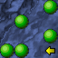 |
|
The sprite is drawn in various positions over the image to produce this:
| Intended Result |
|---|
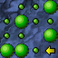 |
Technique
When preparing the sprite, the colors are very important. The mask pixels are 0 (black) wherever the corresponding sprite pixel is to be displayed, and 1 (white) wherever the background needs to be preserved. The sprite must be 0 (black) anywhere where it is supposed to be transparent, but note that black can be used in the non-transparent regions.
In the first blit, the mask is blitted onto the background using the raster operator of AND. Because any value ANDed with 0 equals 0, and any value ANDed with 1 is unchanged, black areas are created where the actual sprites will appear, while leaving the rest of the background alone.
| Result of the first blit |
|---|
 |
In the second blit, the sprite is blitted onto the newly altered background using the raster operator of OR. Because any value ORed with 0 is unchanged, the background is unaffected and the black areas are filled with the actual sprite image.
| Final result |
|---|
| |
It is also possible to achieve the same effect using a sprite with a white background and a white-on-black mask. In this case, the mask would be ORed first, and the sprite ANDed next.
Blitting vs hardware sprites
Blitting is similar to hardware-sprite drawing, in that both systems reproduce a pattern, typically a square area, at different locations on the screen. Hardware sprites have the advantage of being stored in separate memory, and therefore don't disturb the main display memory. This allows them to be moved about the display, covering the "background", with no effect on it.
Blitting moves the same types of patterns about the screen, but does so by writing into the same memory as the rest of the display. This means every time the pattern is placed on the screen, the display "under" it is overwritten, or "damaged". It is up to the software to clean this damage up by blitting twice, once to remove the damage, and then again to place the bit in its new location. However, there are several ways to optimize this. If large areas of the screen are taken over by the patterns, it may be more efficient to blit the background to the screen instead of erasing each pattern individually. A variation involves dividing the screen into segments and erasing only the segments where patterns have been drawn on. This technique is known as dirty rectangles.
As one might imagine, this makes blitting significantly slower than sprite manipulation. However, blitting has one very big advantage: there is no physical limit to the number of patterns you can blit, or to the size of the patterns. Thus you can use blitting to display anything on the screen, including simulating sprites (through the double-write pattern noted above), or even text.
See also
References
- 1 2 Sanchez, Julio; Maria P. Canton (2007). "Displaying Bit-Mapped images". Software solutions for engineers and scientists. CRC Press. p. 690.
External links
- Performance demonstration coded in Flash/AS3
- Xerox Inter-Office Memorandum 19 November 1975
- Squeak: A BitBlt explanation