Base transceiver station
A base transceiver station (BTS) is a piece of equipment that facilitates wireless communication between user equipment (UE) and a network. UEs are devices like mobile phones (handsets), WLL phones, computers with wireless Internet connectivity. The network can be that of any of the wireless communication technologies like GSM, CDMA, wireless local loop, Wi-Fi, WiMAX or other wide area network (WAN) technology.
BTS is also referred to as the radio base station (RBS), node B (in 3G Networks) or, simply, the base station (BS). For discussion of the LTE standard the abbreviation eNB for evolved node B is widely used.
Though the term BTS can be applicable to any of the wireless communication standards, it is generally associated with mobile communication technologies like GSM and CDMA. In this regard, a BTS forms part of the base station subsystem (BSS) developments for system management. It may also have equipment for encrypting and decrypting communications, spectrum filtering tools (band pass filters), etc. antennas may also be considered as components of BTS in general sense as they facilitate the functioning of BTS. Typically a BTS will have several transceivers (TRXs) which allow it to serve several different frequencies and different sectors of the cell (in the case of sectorised base stations). A BTS is controlled by a parent base station controller via the base station control function (BCF). The BCF is implemented as a discrete unit or even incorporated in a TRX in compact base stations. The BCF provides an operations and maintenance (O&M) connection to the network management system (NMS), and manages operational states of each TRX, as well as software handling and alarm collection. The basic structure and functions of the BTS remains the same regardless of the wireless technologies.
General architecture
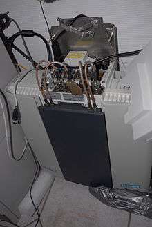
A BTS is usually composed of:
- Transceiver (TRX)
- Quite widely referred to as the driver receiver (DRX), DRX are either in form of single (sTRU), double(dTRU) or a composite double radio unit (DRU). It basically does transmission and reception of signals. It also does sending and reception of signals to and from higher network entities (like the base station controller in mobile telephony).
- Power amplifier (PA)
- Amplifies the signal from DRX for transmission through antenna; may be integrated with DRX.
- Combiner
- Combines feeds from several DRXs so that they could be sent out through a single antenna. Allows for a reduction in the number of antenna used.
- Multiplexer
- For separating sending and receiving signals to/from antenna. Does sending and receiving signals through the same antenna ports (cables to antenna).
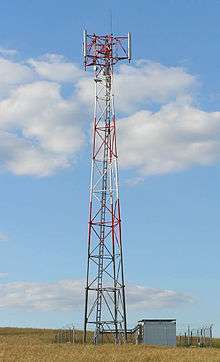
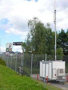
- Antenna
- This is the structure that the BTS lies underneath; it can be installed as it is or disguised in some way (Concealed cell sites).
- Alarm extension system
- Collects working status alarms of various units in the BTS and extends them to operations and maintenance (O&M) monitoring stations.
- Control function
- Controls and manages the various units of BTS, including any software. On-the-spot configurations, status changes, software upgrades, etc. are done through the control function.
- Baseband receiver unit (BBxx)
- Frequency hopping, signal DSP.
Terms regarding a mobile BTS
- Diversity techniques
- To improve the quality of the received signal, often two receiving antennas are used, placed at a distance equal to an odd multiple of a quarter of the corresponding wavelength. For 900 MHz, this wavelength is 30 cm. This technique, known as antenna diversity or space diversity, avoids interruption caused by path fading. The antennas can be spaced horizontally or vertically. Horizontal spacing requires more complex installation, but brings better performance.
- Other than antenna or space diversity, there are other diversity techniques such as frequency/time diversity, antenna pattern diversity, and polarization diversity.
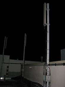
- Splitting refers to the flow of power within a particular area of the cell, known as a sector. Every field can therefore be considered like one new cell.
Directional antennas reduce LoRa (Long Range) interference. If not sectorised, the cell will be served by an omnidirectional antenna, which radiates in all directions. A typical structure is the trisector, also known as clover, in which there are three sectors served by separate antennas. Each sector has a separate direction of tracking, typically of 120° with respect to the adjacent ones. Other orientations may be used to suit the local conditions. Bisectored cells are also implemented. These are most often oriented with the antennas serving sectors of 180° separation to one another, but again, local variations do exist.
See also
Further reading
- Satoshi Maruyama; Katsuhiko Tanahashi; Takehiko Higuchi (2002). Base Transceiver Station for W-CDMA System (PDF). FUJITSU Sci. Tech. J. p. 7.
External links
| Wikimedia Commons has media related to Mobile phone base stations. |