Ball-and-disk integrator
The ball-and-disk integrator is a key component of many advanced mechanical computers. Through simple mechanical means, it performs continual integration of the value of an input. Typical uses were the measurement of area or volume of material in industrial settings, range-keeping systems on ships, and tachometric bombsights. The addition of the torque amplifier by Vannevar Bush led to the differential analysers of the 1930s and 1940s.
History
Invention and early use
The basic concept of the ball-and-disk integrator was first described by James Thomson, brother of William Thomson, 1st Baron Kelvin. William used the concept to build the Harmonic Analyser in 1886. This system was used to calculate the coefficients of a Fourier series representing inputs dialled in as the positions of the balls. The inputs were set to measured tide heights from any port being studied. The output was then fed into a similar machine, the Harmonic Synthesiser, which spun several wheels to represent the phase of the contribution from the sun and moon. A wire running along the top of the wheels took the maximum value, which represented the tide in the port at a given time.[1] Thomson mentioned the possibility of using the same system as a way to solve differential equations, but realized that the output torque from the integrator was too low to drive the required downstream systems of pointers.[1]
A number of similar systems followed, notably those of Leonardo Torres y Quevedo, a Spanish physicist who built several machines for solving real and complex roots of polynomials; and Michelson and Stratton, whose Harmonic Analyser performed Fourier analysis, but using an array of 80 springs rather than Kelvin integrators. This work led to the mathematical understanding of the Gibbs phenomenon of overshoot in Fourier representation near discontinuities.[1]
Military computers
By the turn of the 20th century, naval ships were starting to mount guns with over-the-horizon range. At these sorts of distances, spotters in the towers could not accurately estimate range by eye, leading to the introduction of ever more complex range finding systems. Additionally, the gunners could no longer directly spot the fall of their own shot, relying on the spotters to do this and relay this information to them. At the same time the speed of the ships was increasing, consistently breaking the 20 knot barrier en masse around the time of the introduction of the Dreadnought in 1906. Centralized fire control followed in order to manage the information flow and calculations, but calculating the firing proved to be very complex and error prone.
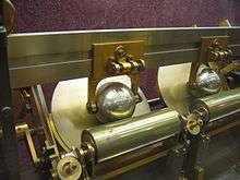
The solution was the Dreyer table , which used a large ball-and-disk integrator as a way to compare the motion of the target relative to the ship, and thereby calculate its range and speed. Output was to a roll of paper. The first systems were introduced around 1912 and installed in 1914. Over time, the Dreyer system added more and more calculators, solving for the effects of wind, corrections between apparent and real wind speed and direction based on the ships motion, and similar calculations. By the time the Mark V systems were installed on later ships after 1918, the system might have as many as 50 people operating it in concert.
Similar devices soon appeared in other navies and for other roles. The US Navy used a somewhat simpler device known as the Rangekeeper, but this also saw continual modification over time and eventually turned into a system of equal or greater sophistication to the UK versions. A similar calculator formed the basis of the Torpedo Data Computer, which solved the more demanding problem of the very long engagement times of torpedo fire.
A well-known example is the Norden bombsight which used a slight variation on the basic design, replacing the ball with another disk. In this system the integrator was used to calculate the relative motion of objects on the ground given the altitude, airspeed, and heading. By comparing the calculated output with the actual motion of objects on the ground, any difference would be due to the effects of wind on the aircraft. Dials setting these values were used to zero out any visible drift, which resulted in accurate wind measurements, formerly a very difficult problem.
Ball disk integrators were used in the analog guidance computers of ballistic missile weapon systems as late as the mid 1970’s. The Pershing 1 missile system, utilized the Bendix ST-120 inertial guidance platform, combined with a mechanical analog computer, to achieve accurate guidance. The ST-120 provided accelerometer information for all three axes. The accelerometer for forward movement transmitted its position to the ball position radial arm, causing the ball fixture to move away from the disk center as acceleration increased. The disk itself represents time and rotates at a constant rate. As the ball fixture moves further out from the center of the disk, the ball spins faster. The ball speed represents the missile speed, the number of ball rotations represent distance traveled. These mechanical positions were used to determine staging events, thrust termination, and warhead separation, as well as "good guidance" signals used to complete the arming chain for the warhead. The first known use of this general concept was in the V-2 missile developed by the Von Braun group at Peenemunde. See PIGA Accelerometer. It was later refined at Redstone Arsenal and applied to the Redstone rocket and subsequently Pershing 1.
Description
The basic mechanism consisted of three moving parts, an input shaft, an output disk, and some sort of roller or disk between the two. Generally the input shaft was electrically driven and used some sort of governor to ensure it spun at a constant speed. The output was a metal disk on a shaft that was arranged at right angles to the input. That is, if the input shaft was vertically aligned, the output shaft would be horizontal, with the disk on the end of the output shaft lying vertically beside the input.
Key to the system's mechanical operation was some sort of system to transmit forces from the input to the output. This was typically a ball bearing positioned between the input shaft and output disk and pressed against both. When the input shaft turned, this caused the bearing to rotate in the opposite direction, and in turn caused the output disk to rotate in the original direction again, passing this on to the shaft it was connected to.
The bearing was mounted on a rack that allowed it to be moved up and down the output disk. The ratio of input to output gearing was a function of the location on the disk; moving the bearing away from the output shaft slowed its rotation relative to the input. The bearing was attached to an instrument that measured the value to be integrated, causing the output shaft's rotation to change based on the input.
For example, in a system measuring the total water flowing through a sluice, a float would be attached to an integrator positioned above the float so the bearing moved up and down with the level of the water. As the water level rose, the bearing would be pushed closer to the center of the output shaft, increasing the output rotation rate. By multiplying the total number of turns on the output, generally measured with an odometer-type counter, by the cross-sectional area of the sluice, the total amount of water flowing past the meter can be calculated.
References
- 1 2 3 Girvan 2003.
Bibliography
- Ray Girvan, "The revealed grace of the mechanism: computing after Babbage", Scientific Computing World, May/June 2003