Axial fan design
An axial fan is a type of a compressor that increases the pressure of the air flowing through it. The blades of the axial flow fans force air to move parallel to the shaft about which the blades rotate. In other words, the flow is axially in and axially out, linearly, hence their name. The design priorities in an axial fan revolve around the design of the propeller that creates the pressure difference and hence the suction force that retains the flow across the fan. The main components that need to be studied in the designing of the propeller include the number of blades and the design of each blade. Their applications include propellers in aircraft, helicopters, hovercraft, ships and hydrofoils. They are also used in wind tunnels and cooling towers. If the propeller is exercising propulsion, then efficiency is the only parameter of interest and other parameters like power required and flow rate are considered of no interest. In case the propeller is used as a fan, the parameters of interest includes power, flow rate, pressure rise and efficiency.[1]
An axial fan consists of much fewer blades i.e., two to six, as compared to ducted fans. Axial fans operate at high specific speed i.e., high flow rate and low head and hence adding more blades will restrict the high flow rate required for its operation. Due to fewer blades, they are unable to impose their geometry on the flow, making the rotor geometry and the inlet and outlet velocity triangles meaningless. Also the blades are made very long with varying blade sections along the radius.
Calculation of parameters
Since the calculation cannot be done using the inlet and outlet velocity triangles, which is not the case in other turbomachines, calculation is done by considering a mean velocity triangle for flow only through an infinitesimal blade element. The blade is divided into many small elements and various parameters are determined separately for each element.[1] There are two theories that solve the parameters for axial fans:[1]
- Slipstream Theory
- Blade Element Theory
Slipstream theory
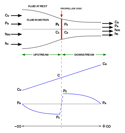
In the figure, the thickness of the propeller disc is assumed to be negligible. The boundary between the fluid in motion and fluid at rest is shown. Therefore, the flow is assumed to be taking place in an imaginary converging duct[1] [2] where:
- D = Diameter of the Propeller Disc.
- Ds = Diameter at the Exit.
| Parameter | Pressure | Density | Velocity | Stagnation enthalpy | Enthalpy |
|---|---|---|---|---|---|
| −∞ | Pa | ρa | Cu (upstream velocity) | hou | hu |
| +∞ | Pa | ρa | Cs (slipstream velocity) | hod | hd |
| Relationship | Equal | Equal | Unequal | Unequal | Equal |
| Comments | Pressure will be atmospheric at both −∞ and +∞ | Density will be equal at both −∞ and +∞ | Velocity will change due to flow across an assumed converging duct | Stagnation enthalpy will be different at −∞ and +∞ | The Enthalpy will be same at −∞ and +∞ as it depends upon the atmospheric conditions that will be the same |
In the figure, across the propeller disc, velocities (C1 and C2) cannot change abruptly across the propeller disc as that will create a shockwave but the fan creates the pressure difference across the propeller disc.[1]
- and


- The area of the propeller disc of diameter D is:

- The mass flow rate across the propeller is:

- Since thrust is change in mass multiplied by the velocity of the mass flow i.e., change in momentum, the axial thrust on the propeller disc due to change in momentum of air, which is:[1]

- Applying Bernoulli's principle upstream and downstream:

On subtracting the above equations:[1]

- Thrust difference due to pressure difference is projected area multiplied by the pressure difference. Axial thrust due to pressure difference comes out to be:

Comparing this thrust with the axial thrust due to change in momentum of air flow, it is found that:[1]

A parameter 'a' is defined such that[1] -
- where


Using the previous equation and "a", an expression for Cs comes out to be:


Now, Ideal Value of Power supplied to the Propeller = Mass flow rate * Change in Stagnation enthalpy;[1]
- where


If propeller was employed to propel an aircraft at speed = Cu; then Useful Power = Axial Thrust * Speed of Aircraft;[1]

- Hence the expression for efficiency comes out to be:[1]

- Let Ds be the diameter of the imaginary outlet cylinder. By Continuity Equation;
- From the above equations it is known that -


Therefore;

Hence the flow can be modeled where the air flows through an imaginary diverging duct, where diameter of propeller disc and diameter of the outlet are related.[1]
Blade element theory

In this theory, a small element (dr) is taken at a distance r from the root of the blade and all the forces acting on the element are analysed to get a solution. It is assumed that the flow through each section of small radial thickness dr is assumed to be independent of the flow through other elements.[1][3]

Resolving Forces in the figure[1] -


Lift Coefficient (CL) and Drag Coefficient (CD) are given as -


Also from the figure [1]-

Now,

No. of Blades (z) and Spacing (s) are related as,[1] and the total thrust for the elemental section of the propeller is zΔFx.

Therefore,[1]


Similarly, solving for ΔFy, ΔFy is found out to be[1] -

and

Finally, thrust and torque can be found out for an elemental section as they are proportional to Fx and Fy respectively.[1]
Performance characteristics
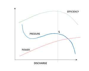
The relationship between the pressure variation and the volume flow rate are important characteristics of fans. The typical characteristics of axial fans can be studied from the performance curves. The performance curve for the axial fan is shown in the figure. (The vertical line joining the maximum efficiency point is drawn which meets the Pressure curve at point "S")[1] The following can be inferred from the curve -
- As the flow rate increases from zero the efficiency increases to a particular point reaches maximum value and then decreases.
- The power output of the fans increases with almost constant positive slope.
- The pressure fluctuations are observed at low discharges and at flow rates(as indicated by the point "S" ) the pressure deceases.
- The pressure variations to the left of the point "S" causes for unsteady flow which are due to the two effects of Stalling and surging.
Causes of unstable flow
Stalling and surging affects the fan performance, blades, as well as output and are thus undesirable. They occur because of the improper design, fan physical properties and are generally accompanied by noise generation.
Stalling effect/Stall
The cause for this is the separation of the flow from the blade surfaces. This effect can be explained by the flow over an air foil. When the angle of incidence increases (during the low velocity flow) at the entrance of the air foil, flow pattern changes and separation occurs. This is the first stage of stalling and through this separation point the flow separates leading to the formation of vortices, back flow in the separated region. For a further the explanation of stall and rotating stall, refer to compressor surge. The stall zone for the single axial fan and axial fans operated in parallel are shown in the figure.[4]
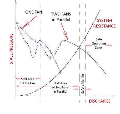
The following can be inferred from the graph :
- For the Fans operated in parallel, the performance is less when compared to the individual fans.
- The fans should be operated in safe operation zone to avoid the stalling effects.
VFDs are not practical for some Axial fans
Many Axial fan failures have happened after controlled blade axial fans were locked in a fixed position and Variable Frequency Drives (VFDs) were installed. The VFDs are not practical for some Axial fans. Axial fans with severe instability regions should not be operated at blades angles, rotational speeds, mass flow rates, and pressures that expose the fan to stall conditions.[5]
Surging effect/Surge
Surging should not be confused with stalling. Stalling occurs only if there is insufficient air entering into the fan blades causing separation of flow on the blade surface. Surging or the Unstable flow causing complete breakdown in fans is mainly contributed by the three factors
- System surge
- Fan surge
- Paralleling
System surge
This situation occurs when the system resistance curve and static pressure curve of the fan intersect have similar slope or parallel to each other. Rather than intersecting at a definite point the curves intersect over certain region reporting system surge. These characteristics are not observed in axial fans.
Fan surge
This unstable operation results from the development of pressure gradients in the opposite direction of the flow. Maximum pressure is observed at the discharge of the impeller blade and minimum pressure on the side opposite to the discharge side. When the impeller blades are not rotating these adverse pressure gradients pump the flow in the direction opposite to the direction of the fan. The result is the oscillation of the fan blades creating vibrations and hence noise.[6]
Paralleling
This effect is seen only in case of multiple fans. The air flow capacities of the fans are compared and connected in same outlet or same inlet conditions. This causes noise, specifically referred to as Beating in case of fans in parallel. To avoid beating use is made of differing inlet conditions, differences in rotational speeds of the fans, etc.
Methods to avoid unsteady flow
By designing the fan blades with proper hub-to-tip ratio and analyzing performance on the number of blades so that the flow doesn't separate on the blade surface these effects can be reduced. Some of the methods to overcome these effects are re-circulation of excess air through the fan, axial fans are high specific speed devices operating them at high efficiency and to minimize the effects they have to be operated at low speeds. For controlling and directing the flow use of guide vanes is suggested. Turbulent flows at the inlet and outlet of the fans cause stalling so the flow should be made laminar to prevent the effect.
Notes
- 1 2 3 4 5 6 7 8 9 10 11 12 13 14 15 16 17 18 19 20 21 22 23 24 25 26 S. M. Yahya (10 October 2010). "14". Turbines Compressors And Fans (4th Edition) (4th ed.). McGraw-Hill Education (India) Pvt Limited. pp. 622–9. ISBN 978-0-07-070702-3. Retrieved 13 May 2013.
- ↑ POOLE, R (1 Jan 1935). "THE THEORY AND DESIGN OF PROPELLER-TYPE FANS." (PDF). ICE Selected Engineering Papers. 1 (178). doi:10.1680/isenp.1935.13442. Retrieved 2013-05-23.
- ↑ Marble, Frank E. (1948). "The Flow of a Perfect Fluid Through an Axial Turbomachine with Prescribed Blade Loading". Journal of the Aeronautical Sciences (Institute of the Aeronautical Sciences). 15 (8): 473–485. doi:10.2514/8.11624. Retrieved 2013-05-23.
- 1 2 "Stall,problems and solutions" (PDF). Retrieved 2013-05-10.
- ↑ https://www1.eere.energy.gov/manufacturing/tech_assistance/pdfs/fan_sourcebook.pdf U.S. Dept. of Energy, Improving Fan System Performance, Page 35 (39/92), Last paragraph
- ↑ "System Surge, Fan Surge and Paralleling" (PDF). Retrieved 2013-05-12.
References
- S. M. Yahya (10 October 2010). "14". Turbines Compressors And Fans (4th Edition) (4th ed.). McGraw-Hill Education (India) Pvt Limited. pp. 622–628. ISBN 978-0-07-070702-3. Retrieved 13 May 2013.
- Theodore Theodorsen (1948). Theory of propellers. McGraw-Hill Book Co. Retrieved 23 May 2013.
- Meyer, C.J.; D.G. Kröger (10 Aug 2001). "Numerical simulation of the flow field in the vicinity of an axial flow fan" (PDF). International Journal for Numerical Methods in Fluids. 36 (8): 947–969. doi:10.1002/fld.161. Retrieved 2013-05-23.
- Lanzafame, R.; M. Messina (Nov 2007). "Fluid dynamics wind turbine design: Critical analysis, optimization and application of BEM theory". Elsevier: Renewable Energy. 32 (14): 2291–2305. doi:10.1016/j.renene.2006.12.010. Retrieved 2013-05-23.
- GEORGE W. STICKLE; JOHN L.CRIGLER (19 July 1940). "PROPELLER ANALYSIS FROM EXPERIMENTAL DATA" (PDF). NATIONAL ADVISORY COMMITTEE FOR AERONAUTICS. Retrieved 2013-05-23.
- Marble, Frank E. (1948). "The Flow of a Perfect Fluid Through an Axial Turbomachine with Prescribed Blade Loading". Journal of the Aeronautical Sciences (Institute of the Aeronautical Sciences). 15 (8): 473–485. doi:10.2514/8.11624. Retrieved 2013-05-23.
- POOLE, R (1 Jan 1935). "THE THEORY AND DESIGN OF PROPELLER-TYPE FANS." (PDF). ICE Selected Engineering Papers. 1 (178). doi:10.1680/isenp.1935.13442. Retrieved 2013-05-23.
- A. B. McKenzie (1997). Axial flow fans and compressors: aerodynamic design and performance. Ashgate Publishing, Limited. ISBN 978-0-291-39850-5. Retrieved 23 May 2013.
- Naizi, Saied (July 2000). "NUMERICAL SIMULATION OF ROTATING STALL AND SURGE ALLEVIATION IN AXIAL COMPRESSORS" (PDF). Thesis at Georgia Institute of Technology. Retrieved 2013-05-23.
- "System Surge, Fan Surge and Paralleling" (PDF). Retrieved 2013-05-12.
- "Understanding Fan Performance Curves" (PDF). Retrieved 2013-05-10.
- "Stall,problems and solutions" (PDF). Retrieved 2013-05-10.
- "Surge, stall, and instabilities in fans". Retrieved 2013-05-10.
See also
- Mechanical fan
- Propeller (marine)
- Propeller (aircraft)
- Industrial fan
- Ceiling fan
- Turbofan
- Ducted propeller
- Window fan
- Compressor surge
- Compressor stall
- Propeller walk
- Cavitation
- Azimuth thruster
- Kitchen rudder
- Paddle steamer
- Propulsor
- Cleaver
- Folding propeller
- Modular propeller
- Supercavitating propeller