Automatic control

Automatic control in engineering and technology is a wide generic term covering the application of mechanisms to the operation and regulation of processes without continuous direct human intervention.
It covers the range of application from a household thermostat controlling a boiler, to a large industrial control system with tens of thousands of input measurements and output control signals. In control complexity it can range from simple on-off control to multi-variable high level algorithms.
In the simplest type of an automatic control loop, a controller compares a measured value of a process with a desired set value, and processes the resulting error signal to change some input to the process, in such a way that the process stays at its set point despite disturbances. This closed-loop control is an application of negative feedback to a system. The mathematical basis of control theory was begun in the 18th century, and advanced rapidly in the 20th.
Open-loop and closed-loop (feedback) control
Fundamentally, there are two types of control loop; open loop control, and closed loop (feedback) control.
In open loop control, the control action from the controller is independent of the "process output" (or "controlled process variable"). A good example of this is a central heating boiler controlled only by a timer, so that heat is applied for a constant time, regardless of the temperature of the building. (The control action is the switching on/off of the boiler. The process output is the building temperature).
In closed loop control, the control action from the controller is dependent on the process output. In the case of the boiler analogy this would include a thermostat to monitor the building temperature, and thereby feed back a signal to ensure the controller maintains the building at the temperature set on the thermostat. A closed loop controller therefore has a feedback loop which ensures the controller exerts a control action to give a process output the same as the "Reference input" or "set point". For this reason, closed loop controllers are also called feedback controllers.[1]
The definition of a closed loop control system according to the British Standard Institution is 'a control system possessing monitoring feedback, the deviation signal formed as a result of this feedback being used to control the action of a final control element in such a way as to tend to reduce the deviation to zero.' " [2]
Likewise; "A Feedback Control System is a system which tends to maintain a prescribed relationship of one system variable to another by comparing functions of these variables and using the difference as a means of control.'"[3]
The advanced type of automation that revolutionized manufacturing, aircraft, communications and other industries, is feedback control, which is usually continuous and involves taking measurements using a sensor and making calculated adjustments to keep the measured variable within a set range.[4] The theoretical basis of closed loop automation is control theory.
Control actions
The control action is the form of the controller output action.
Discrete control (on/off)
One of the simplest types of control is on-off control. An example is the thermostat used on household appliances which either opens or closes an electrical contact. (Thermostats were originally developed as true feedback-control mechanisms rather than the on-off common household appliance thermostat.)
Sequence control, in which a programmed sequence of discrete operations is performed, often based on system logic that involves system states. An elevator control system is an example of sequence control.
PID controller
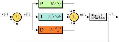
A proportional–integral–derivative controller (PID controller) is a control loop feedback mechanism (controller) widely used in industrial control systems.
A PID controller continuously calculates an error value as the difference between a desired setpoint and a measured process variable and applies a correction based on proportional, integral, and derivative terms, respectively (sometimes denoted P, I, and D) which give their name to the controller type.

The theoretical understanding and application dates from the 1920s, and they are implemented in nearly all analogue control systems; originally in mechanical controllers, and then using discrete electronics and latterly in industrial process computers.
Programmable logic controller
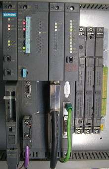
PLCs can range from small "building brick" devices with tens of I/O in a housing integral with the processor, to large rack-mounted modular devices with a count of thousands of I/O, and which are often networked to other PLC and SCADA systems.
They can be designed for multiple arrangements of digital and analog inputs and outputs (I/O), extended temperature ranges, immunity to electrical noise, and resistance to vibration and impact. Programs to control machine operation are typically stored in battery-backed-up or non-volatile memory.
It was from the automotive industry in the USA that the PLC was born. Before the PLC, control, sequencing, and safety interlock logic for manufacturing automobiles was mainly composed of relays, cam timers, drum sequencers, and dedicated closed-loop controllers. Since these could number in the hundreds or even thousands, the process for updating such facilities for the yearly model change-over was very time consuming and expensive, as electricians needed to individually rewire the relays to change their operational characteristics.
When digital computers became available, being general-purpose programmable devices, they were soon applied to control sequential and combinatorial logic in industrial processes. However these early computers required specialist programmers and stringent operating environmental control for temperature, cleanliness, and power quality. To meet these challenges this the PLC was developed with several key attributes. It would tolerate the shop-floor environment, it would support discrete (bit-form) input and output in an easily extensible manner, it would not require years of training to use, and it would permit its operation to be monitored. Since many industrial processes have timescales easily addressed by millisecond response times, modern (fast, small, reliable) electronics greatly facilitate building reliable controllers, and performance could be traded off for reliability.[5]
Examples
Automatic control can self-regulate a technical plant (such as a machine or an industrial process) operating condition or parameters by the controller with minimal human intervention. A regulator such as a thermostat is an example of a feedback controller. Another possible example of Automatic Control are the ABS of a car.
History of automatic Control
Ancient Greece
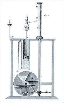
It was a preoccupation of the Greeks and Arabs (in the period between about 300 BC and about 1200 AD) to keep accurate track of time. In about 270 BC the Greek Ctesibius invented a float regulator for a water clock, a device not unlike the ball and cock in a modern flush toilet. The invention of the mechanical clock in the 14th century made the water clock and its feedback control system obsolete. The float regulator does not appear again until its use in the Industrial Revolution.
Industrial Revolution in Europe
Thomas Newcomen invented the steam engine in 1713, and this date marks the accepted beginning of the Industrial Revolution; however, its roots can be traced back into the 17th century. The introduction of prime movers, or self-driven machines advanced grain mills, furnaces, boilers, and the steam engine created a new requirement for automatic control systems including temperature regulators (invented in 1624 (see Cornelius Drebbel)), pressure regulators (1681), float regulators (1700) and speed control devices. The design of feedback control systems up through the Industrial Revolution was by trial-and-error, together with a great deal of engineering intuition. Thus, it was more of an art than a science. In the mid-19th century mathematics was first used to analyze the stability of feedback control systems. Since mathematics is the formal language of automatic control theory, we could call the period before this time the prehistory of control theory.
First and Second World Wars
The First and Second World Wars saw major advancements in the field of mass communication and signal processing. Other key advances in automatic controls include differential equations, stability theory and system theory (1938), frequency domain analysis (1940), ship control (1950), and stochastic analysis (1941).
Space/computer age
With the advent of the space age in 1957, controls design, particularly in the United States, turned away from the frequency-domain techniques of classical control theory and backed into the differential equation techniques of the late 19th century, which were couched in the time domain. The modern era saw time-domain design for nonlinear systems (1961), navigation (1960), optimal control and estimation theory (1962), nonlinear control theory (1969), digital control and filtering theory (1974), and the personal computer (1983).
See also
- Control theory
- Process control
- Controller (control theory)
- Control engineering
- PID loop
- VisSim
- EICASLAB
- Feedback
- Feedforward Control
References
- ↑ "Feedback and control systems" - JJ Di Steffano, AR Stubberud, IJ Williams. Schaums outline series, McGraw-Hill 1967
- ↑ Mayr, Otto (1970). The Origins of Feedback Control. Clinton, MA USA: The Colonial Press, Inc.
- ↑ Mayr, Otto (1969). The Origins of Feedback Control. Clinton, MA USA: The Colonial Press, Inc.
- ↑ Bennett, Stuart (1992). A history of control engineering, 1930-1955. IET. p. p. 48. ISBN 978-0-86341-299-8.
- ↑ E. A. Parr, Industrial Control Handbook, Industrial Press Inc., 1999 ISBN 0-8311-3085-7
Further reading
- V. Gurevich "Electronic Devices on Discrete Components for Industrial and Power Engineering", CRC Press, New York, 2008, 418 p.
- Tang Bingxin "Fundamentals of Control Engineering", 37 p.
- https://web.archive.org/web/20100420113249/http://www.tpub.com:80/content/doe/h1013v2/css/h1013v2_112.htm