Airlift pump
An airlift pump is a pump that has low suction and moderate discharge of liquid and entrained solids. The pump injects compressed air at the bottom of the discharge pipe which is immersed in the liquid. The compressed air mixes with the liquid causing the air-water mixture to be less dense than the rest of the liquid around it and therefore is displaced upwards through the discharge pipe by the surrounding liquid of higher density. Solids may be entrained in the flow and if small enough to fit through the pipe, will be discharged with the rest of the flow at a shallower depth or above the surface. Airlift pumps are widely used in aquaculture to pump, circulate and aerate water in closed, recirculating systems and ponds.[1] Other applications include dredging, underwater archaeology, salvage operations and collection of scientific specimens.
Principle
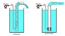
The only energy required is provided by compressed air. This air is usually compressed by a compressor or a blower. The air is injected in the lower part of a pipe that transports a liquid. By buoyancy the air, which has a lower density than the liquid, rises quickly. By fluid pressure, the liquid is taken in the ascendant air flow and moves in the same direction as the air. The calculation of the volume flow of the liquid is possible thanks to the physics of two-phase flow.
Utilization
Airlift pumps are often used in deep dirty wells where sand would quickly abrade mechanical parts. (The compressor is on the surface and no mechanical parts are needed in the well). However airlift wells must be much deeper than the water table to allow for submergence. Air is generally pumped at least as deep under the water as the water is to be lifted. (If the water table is 50 ft below, the air should be pumped 100 feet deep).
It is also sometimes used in part of the process on a wastewater treatment plant if a small head is required (typically around 1 foot head).
Airlifts are used to collect fauna samples from sediment.[2] Airlifts can oversample zooplankton and meiofauna but undersample animals that exhibit an escape response.[2]
Inventor
The first airlift pump is considered to be invented by the German engineer Carl Emanuel Löscher, who lived in the second part of the eighteenth century. He discovered the airlift pump in 1797.
Advantages and disadvantages
Advantages
- The pump is very reliable. The very simple principle is a clear advantage. Only air with a higher pressure than the liquid is required.
- The liquid is not in contact with any mechanical elements. Therefore, neither the pump can be abraded (which is important for sandwater wells), nor the contents in the pipe (which is important for archeological research in the sea).
- Act as a water aerator and can in some configurations lift stagnant bottom water to the surface (of water tanks).
- Since there are no restrictive pump parts, solids up to 70% of the pipe diameter can be reliably pumped.
Disadvantages
- Cost: while in some specific case the operational cost can be interesting, most of the time, the quantity of air to compress is high compared to the liquid flow required.[3][4]
- Conventional airlift pumps have a flow rate that is very limited. The pump is either on or off. It is very difficult to get a wide range of proportional flow control by varying the volume of compressed air. This is a dramatic disadvantage in some parts of a small wastewater treatment plant, such as the aerator.[5]
- The suction is limited.
- This pumping system is suitable only if the head is relatively low. If you want to obtain a high head, you have to choose a conventional pumping system.
- Because of the principle, a lot of air remains in the liquid. In certain case, this can be problematic, as, for example, in a waste water treatment plant, before an anaerobic basin.
Design improvements
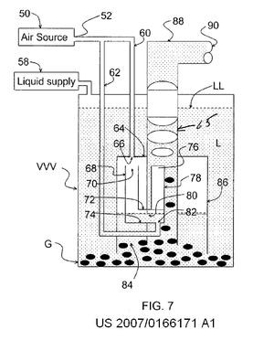
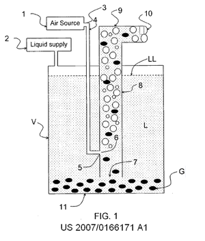
A recent (2007) variant called the "geyser pump" can pump with greater suction and less air. It also pumps proportionally to the air flow, permitting use in processes that require varying controlled flows. It arranges to store up the air, and release it in large bubbles that seal to the lift pipe, raising slugs of fluid.[6]
See also
Notes and references
- ↑ AIRLIFTEN
- 1 2 Cahoon, LB; Lindquist, DG; Clavijo, IE; Tronzo, CR (1992). "Sampling small invertebrates at the sediment-water interface". In: Cahoon, LB. (ed.) Proceedings of the American Academy of Underwater Sciences Twelfth Annual Scientific Diving Symposium "Diving for Science 1992". Held September 24–27, 1992 at the University of North Carolina at Wilmington, Wilmington, NC. American Academy of Underwater Sciences. Retrieved 2013-04-05.
- ↑ "Air quantity calculation" (PDF). (1.86 MB)
- ↑ Airlift basic calculation
- ↑ New Pump Technology May Improve Small Flows, WVU NCSFC Clearinghouse Accessed 2011-3-21
- ↑ Patent Application number: 11/654,448, January 17, 2007, Inventor: Masao Kondo