ASC-15
The ASC-15 (Advance System Controller Model 15) was a digital computer developed by International Business Machines (IBM) for use on the Titan II intercontinental ballistic missile (ICBM).[1][2] It was subsequently modified and used on the Titan III and Saturn I Block II launch vehicles.
Its principal function on these rockets was to make navigation calculations using data from inertial sensor systems. It also performed readiness checks before launch.[3] It was a digital serial processor using fixed-point data with 27-bit words. The storage was a drum memory. Electronic circuits were welded encapsulated modules, consisting of discrete resistors, transistors, capacitors, and other components welded together and encapsulated in a foam material. It was manufactured in the IBM plant at Owego, NY.[4]
ASC-15 for Titan II
The first inertial guidance system for the Titan II was built by AC Spark Plug, and included an inertial measurement unit based in designs from Draper Labs at MIT and the ASC-15 computer designed and built by IBM in Owego, NY. The first Titan II missile carrying this system was launched 16 March 1962. Acquiring spares for this system became difficult, and the Air Force decided to replace it with a new system. The AC Spark Plug system, including the ASC-15, was replaced by the Delco Electronics Universal Space Guidance System (USGS) on operational Titan II missiles starting in January 1978.[5] The guidance computer in the USGS was the Magic 352, made by Delco.[6]
The ASC-15 was built on an aluminum frame about 1.5x1.5x1 feet.[7] The sides, top and bottom were covered by pieces of laminated plastic, covered with gold-plated aluminum foil. These covers were slightly convex and ribbed for stiffness. Inside the covers were fifty-two logic sticks, each containing four welded encapsulated modules. These surrounded a bell frame housing a drum memory.[8] See Figure 2.
The drum was a thin-walled stainless steel cylinder 3 inches long and 4.5 inches in diameter covered with a magnetic nickel-cobalt alloy. It was driven by a synchronous motor at 6,000 rpm. The drum had 70 tracks, of which 58 were used and 12 were spare. These tracks were used as follows:
| NO. TRACKS | USE OF TRACKS |
|---|---|
| 34 | Instruction tracks |
| 7 | Constants |
| 8 | Target data |
| 2 | Data for temporary storage |
| 5 | Revolvers for extra fast access storage |
| 2 | Timing tracks |
The capacity of a track was 1,728 bits. Instruction words were 9-bits long, and data was stored in 27-bit words.[9]
Coincident with 58 tracks were 67 read heads and 13 write heads. While the drum was spinning at 6,000 rpm, the heads floated above the surface of the drum on a thin layer of air. When the drum was spinning up or slowing down, the heads were raised off the drum by camshafts rotated by a chain that was driven by a motor on top of the drum housing, to avoid scoring the magnetic surface. See Figure 3.
ASC-15 for Titan III
The Titan III was a space launch vehicle based on the Titan II ICBM. The ASC-15 was kept as the vehicle guidance computer, but the drum was lengthened slightly to provide 78 usable tracks, an increase of 20 over the drum used in the Titan II. The memory held 9,792 instructions (51 tracks) and 1,152 constants (18 tracks). The speed was the same as for the Titan II: 100 revolutions/second × 64 words/revolution × 27 bits/word = 172.8 kilobits/second. The time for an addition operation was 156 µs; for a multiplication, 1,875 µs; and for a division, 7,968 µs.[10]
ASC-15 for Saturn I
No guidance computer was used for Saturn I Block I (missions SA-1, 2, 3 and 4). The guidance system for SA-2 is shown in Figure 4.[11] The pitch program was provided by a cam device located in the Servo Loop Amplifier Box. The sequence of events was controlled by a program device that was also used on Jupiter missiles. This was a 6-track tape recorder that sent pulses to a set of relays (the flight sequencer) to activate and deactivate various circuits in a precisely timed sequence.
The ASC-15 was first flown on SA-5, the first Saturn I Block II vehicle and the first to achieve orbit.[12] It was a passenger on this mission, not guiding the vehicle but generating test data for later evaluation. The active guidance system on SA-5 was similar to that of earlier flights. The passenger system was the ASC-15 and the ST-124 inertial platform. Guidance was open loop; that is guidance commands were functions only of time. SA-5 also saw the introduction of the Instrument Unit.
On SA-6, while open loop ST-90S guidance was used for the first stage (S-I), after separation the ST-124 and ASC-15 used path adaptive guidance (closed loop) to control the second stage (S-IV). The SA-6 guidance system is shown in Figure 5.[13] The effectiveness of the path adaptive guidance was demonstrated inadvertently when premature shutdown of S-IV engine number eight had virtually no effect on the vehicle trajectory.
The arrangement of the ST-90S and ST-124 systems (including the ASC-15 guidance computer) on SA-6 is shown in Figure 6.[14] This is version 1 of the Instrument Unit, which flew on SA-5, 6, and 7.
On SA-7 the ST-124 system guided the firing of both stages. The guidance and control system for SA-7 is shown in Figure 7.[15] The digital computer is the ASC-15. It replaced both the cam device that contained the S-I tilt program for earlier missions.[16] and the program device that controlled the sequence of events on those missions.
The next mission flown after SA-7 was SA-9. It carried a new version of the Instrument Unit, one that was unpressurized and 2 feet (0.61 m) shorter than version 1. Version 2 flew on the remaining Saturn I missions (SA-8, 9, and 10), and is shown under construction at MSFC in Figure 8.[17] Figure 9 is a blowup of this image, showing the dummy ASC-15 and dummy ST-124.
Gallery
-
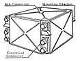
Missile Guidance Computer (MGC) for Titan II.
-

Exploded view of MGC.
-

Drum memory of the ASC-15
-

SA-2 control system
-

SA-6 guidance and control system
-

Instrument Unit for SA-6
-

SA-7 guidance and control system
-
.jpg)
SA-8 instrument unit under construction at MSFC
-

Detail of SA-8 instrument unit, with dummies marked for ASC-15 and ST-124.
References
- USAF Sheppard Technical Training Center. "Student Study Guide, Missile Launch/Missile Officer (LGM-25)." May 1967. Pages 61–65. Available at WikiMedia Commons: TitanII MGC.pdf
- David K. Stumpf. Titan II: A History of a Cold War Missile Program. The University of Arkansas Press, 2000. Pages 63–65
- Bilstein, Roger E. (1980). Stages to Saturn: A Technological History of the Apollo/Saturn Launch Vehicles. NASA SP-4206. ISBN 0-16-048909-1. Available on-line: HTML or PDF
- Olsen, P.F. and Orrange, R.J. "Real-Time Systems for Federal Applications. A Review of Significant Technological Developments," in IBM J. Res. Develop. Vol 25, No. 5, September 1981. http://www.research.ibm.com/journal/rd/255/ibmrd2505F.pdf
- A.E. Cooper and W.T. Chow. "Development of On-board Space Computer Systems" IBM Journal of Research and Development, January 1976. Pages 5–18.
- Larson, Paul O. "Titan III Inertial Guidance System," in AIAA Second Annual Meeting, San Francisco, 26–29 July 1965, pages 1–11.
- Liang, A.C. and Kleinbub, D.L. "Navigation of the Titan IIIC space launch vehicle using the Carousel VB IMU". AIAA Guidance and Control Conference, Key Biscayne, FL, 20–22 August 1973. AIAA Paper No. 73-905.
- "Saturn I Summary." NASA MSFC, 15 Feb 1966. 43 pages. hdl:2060/19660014308
- Brandner, F.W. "Technical Information Summary Concerning Saturn Vehicle SA-2." http://ntrs.nasa.gov/archive/nasa/casi.ntrs.nasa.gov/19650076118_1965076118.pdf. NASA MSFC Memo dated 5 April 1962. TMX 51831. 16 pages.
- Saturn Flight Evaluation Working Group. "Results of the Fifth Saturn I Launch Vehicle Test Flight (SA-5)." NASA MSFC 22 September 1964. MPR-SAT-FE-64-17. http://ntrs.nasa.gov/archive/nasa/casi.ntrs.nasa.gov/19650060677_1965060677.pdf.
- Saturn Flight Evaluation Working Group. "Results of the Sixth Saturn I Launch Vehicle Test Flight (SA-6)." NASA MSFC 1 October 1964. MPR-SAT-FE-64-18. http://ntrs.nasa.gov/archive/nasa/casi.ntrs.nasa.gov/19700089115_1970089115.pdf.
- Saturn Flight Evaluation Working Group. "Results of the Seventh Saturn I Launch Vehicle Test Flight (SA-7)." NASA MSFC 30 December 1964. MPR-SAT-FE-64-19. http://ntrs.nasa.gov/archive/nasa/casi.ntrs.nasa.gov/19740074283_1974074283.pdf.
- "Apollo Systems Reliability Status Report. Volume II: Subsystems Reliability Status DRAFT." NASA, Washington, DC, 23 September 1963. 225 pages. http://ntrs.nasa.gov/archive/nasa/casi.ntrs.nasa.gov/19750069412_1975069412.pdf.
- NASA. "Spaceborne Digital Computer Systems". March 1971. NASA SP-8070.
Notes
- ↑ 1958: "IBM develops the ASC-15 guidance computer for the United States Air Force Titan II missile computer. " IBM Archives: Space flight chronology. Web page at http://www-[] 03.ibm.com/ibm/history/exhibits/space/space_chronology.html. See also Bilstein, Stages to Saturn, p. 243. See also Olsen and Orrange, p. 406
- ↑ http://ed-thelen.org/comp-hist/BRL61-a.html
- ↑ Larson, p. 7
- ↑ Larson, p. 4. See also: Martin H. Weik. "A Third Survey of Domestic Electronic Digital Computing Systems" Ballistic Research Laboratories, Aberdeen Proving Ground, Maryland Report No. 1115, March 1961 http://ed-thelen.org/comp-hist/BRL61-a.html pages 58-59.
- ↑ David K. Stumpf. Titan II. A History of a Cold War Missile Program. University of Arkansas Press, Fayetteville, Arkansas, 2000. ISBN 1-55728-601-9. Pages 63-67.
- ↑ A.C. Liang and D.L. Kleinbub."Navigation of the Titan IIIC space launch vehicle using the Carousel VB IMU." AIAA Guidance and Control Conference, Key Biscayne, FL, 20–22 August 1973. AIAA Paper No. 73-905.
- ↑ Estimate based on mensuration of photographs of the ASC-15 and a volume of 2.12 cubic feet (0.060 m3) reported in "Spaceborne Digital Computer Systems," NASA, SP-8070, March 1971.
- ↑ "Missile Launch/Missile Officer (LGM-25) Missile Systems." USAF, Sheppard Technical Training Center, May 1967. Student Study Guide OBR1821F/3121f-V-1 thru 4, Volume I of II.
- ↑ A.E. Cooper and W.T. Chow. "Development of On-board Space Computer Systems" IBM Journal of Research and Development, January 1976. Pages 5-18.
- ↑ Paul O. Larson. "Titan III Inertial Guidance System". AIAA Paper No. 65-306. AIAA Second Annual Meeting, 26–29 July 1965, San Francisco, CA.
- ↑ F.W. Brandner. "Technical Information Summary Concerning Saturn Vehicle SA-2.". NASA MSFC Memo dated 5 April 1962. TMX 51831. 16 pages http://ntrs.nasa.gov/archive/nasa/casi.ntrs.nasa.gov/19650076118_1965076118.pdf
- ↑ Saturn Flight Evaluation Working Group. "Results of the Fifth Saturn I Launch Vehicle Test Flight (SA-5)." NASA MSFC 22 September 1964. MPR-SAT-FE-64-17. http://ntrs.nasa.gov/archive/nasa/casi.ntrs.nasa.gov/19650060677_1965060677.pdf.
- ↑ Saturn Flight Evaluation Working Group. "Results of the Sixth Saturn I Launch Vehicle Test Flight (SA-6)." NASA MSFC 1 October 1964. MPR-SAT-FE-64-18. http://ntrs.nasa.gov/archive/nasa/casi.ntrs.nasa.gov/19700089115_1970089115.pdf
- ↑ "Apollo Systems Reliability Status Report. Volume II: Subsystems Reliability Status DRAFT." NASA, Washington, DC, 23 September 1963. 225 pages. http://ntrs.nasa.gov/archive/nasa/casi.ntrs.nasa.gov/19750069412_1975069412.pdf
- ↑ Saturn Flight Evaluation Working Group. "Results of the Seventh Saturn I Launch Vehicle Test Flight (SA-7)." NASA MSFC 30 December 1964. MPR-SAT-FE-64-19. http://ntrs.nasa.gov/archive/nasa/casi.ntrs.nasa.gov/19740074283_1974074283.pdf
- ↑ "Saturn I Summary." NASA MSFC, 15 Feb 1966. 43 pages. hdl:2060/19660014308 . "Results of the Seventh Saturn I Launch Vehicle Test Flight (SA-7)." PDF page 113.
- ↑ http://mix.msfc.nasa.gov/IMAGES/HIGH/6412716.jpg. "This image depicts a high angle view of technicians working on the instrument unit (IU) component assembly for the SA-8 mission in Marshall Space Flight Center's building 4705."
External links
- "Titan II missile computer. " IBM Archives: Space flight chronology.
- Martin H. Weik. "A Third Survey of Domestic Electronic Digital Computing Systems" Ballistic Research Laboratories, Aberdeen Proving Ground, Maryland Report No. 1115, March 1961. Pages 58-59. This page includes a link to an image of a welded encapsulated module. It says also that ASC 15 stands for Advance System Controller Model 15.
Guidance computers | |
|---|---|
| On crewed spacecraft | |
| On launch vehicles |
|