AES3
AES3 (also known as AES/EBU) is a standard for the exchange of digital audio signals between professional audio devices. AES3 was jointly developed by the Audio Engineering Society (AES) and the European Broadcasting Union (EBU). An AES3 signal can carry two channels of PCM audio over several transmission media including balanced lines, unbalanced lines, and optical fiber.[1] It was published in 1985 and has been revised in 1992 and 2003.
AES3 has been incorporated into the International Electrotechnical Commission's standard IEC 60958, and is available in a consumer-grade variant known as S/PDIF.
History and development
The development of standards for digitising analog audio, as used to interconnect both professional and domestic audio equipment, began in the late 1970s[2] in a joint effort between the Audio Engineering Society and the European Broadcasting Union, and culminated in the publishing of AES3 in 1985. Early on, the standard was frequently known as AES/EBU. Both AES and EBU versions of the standard exist. Variants using different physical connections—essentially consumer versions of AES3 for use within the domestic "Hi-Fi" environment using connectors more commonly found in the consumer market—are specified in IEC 60958. These variants are commonly known as S/PDIF.
The standard has been revised in 1992 and 2003 and is published in AES and EBU versions. Worldwide, it is the most commonly used method for digitally interconnecting audio equipment.
Hardware connections
The AES3 standard parallels part 4 of the international standard IEC 60958. Of the physical interconnection types defined by IEC 60958, three are in common use.
IEC 60958 Type I—Balanced, XLR
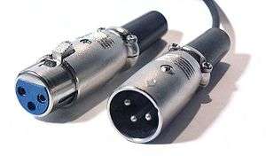
Type I connections use balanced, 3-conductor, 110-ohm twisted pair cabling with XLR connectors. Type I connections are most often used in professional installations and are considered the AES3 standard connector. The hardware interface is usually implemented using RS-422 line drivers and receivers.
| Cable end | Device end | |
|---|---|---|
| Input | XLR male plug | XLR female jack |
| Output | XLR female plug | XLR male jack |
IEC 60958 Type II—Unbalanced, RCA
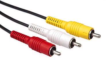
Type II connections use unbalanced, 2-conductor, 75-ohm coaxial cable with RCA connectors. Type II connections are used in most often in consumer audio installations and are often called coaxial S/PDIF connections.
| Cable end | Device end | |
|---|---|---|
| Input | RCA male plug | RCA female jack |
| Output | RCA male plug | RCA female jack |
IEC 60958 Type II Optical—Fiber, F05/TOSLINK
Type II Optical connections use optical fiber—usually plastic, but occasionally glass—with F05 connectors, which are more commonly known by their Toshiba brand name, TOSLINK. Like Type II, Type II Optical connections are also used in consumer audio installations and are often called optical S/PDIF connections.
| Cable end | Device end | |
|---|---|---|
| Input | F05/TOSLINK male plug | F05/TOSLINK female jack |
| Output | F05/TOSLINK male plug | F05/TOSLINK female jack |
Other connections

The AES-3id standard defines a 75-ohm BNC electrical variant of AES3. This uses the same cabling, patching and infrastructure as analogue or digital video, and is thus common in the broadcast industry.
AES3 digital audio format can also be carried over an Asynchronous Transfer Mode network. The standard for packing AES3 frames into ATM cells is AES47.
For information on the synchronization of digital audio structures, see the AES11 standard. The ability to insert unique identifiers into an AES3 bit stream is covered by the AES52 standard.
Relation to S/PDIF
The precursor of the IEC 60958 Type II specification was the Sony/Philips Digital Interface, or S/PDIF. S/PDIF and AES3 are similar in many ways and are interchangeable at the protocol level, but at the physical level they specify different electrical signaling levels and impedances, which may be significant in some applications.
Protocol
- The low-level protocol for data transmission in AES3 and S/PDIF is largely identical, and the following discussion applies for S/PDIF, unless otherwise noted.
AES3 was designed primarily to support stereo PCM encoded audio in either DAT format at 48 kHz or CD format at 44.1 kHz. No attempt was made to use a carrier able to support both rates; instead, AES3 allows the data to be run at any rate, and encoding the clock and the data together using biphase mark code (BMC).
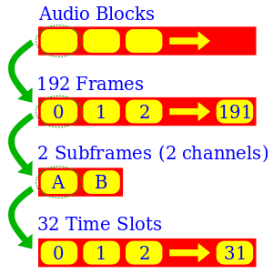
At the highest level, data is issued as consecutive audio blocks; each audio block consists of 192 consecutive frames. Data contained in each frame is collated into metadata for every audio block.
A 64-time-slot frame is issued each sample time; this fact determining the clock rate. The frame is divided into two 32-time-slot subframes each containing one sample; the subframes are used for the channels: A (left) and B (right). Each subframe consists of 32 time slots each of 2 symbols comprising either 1 bit encoded with biphase mark code or synchronisation preamble. In each subframe, audio data may use up to 24 bits.
At the default 48 kHz sample rate, there are 250 audio blocks per second, and 3,072 kilobits per second with a biphase clock of 6.144 MHz [3]
The 32 time slots of each subframe are used as following:
| Time slot | Name | Description |
|---|---|---|
| 0–3 | Preamble | A synchronisation preamble (not biphase mark coded) for audio blocks, frames, and subframes. |
| 4–7 | Auxiliary sample (optional) | A low-quality auxiliary channel used as specified in the channel status word, notably for producer talkback or recording studio-to-studio communication. |
| 8–27, or 4–27 | Audio sample | One sample stored with most significant bit (MSB) last. If the auxiliary sample is used, bits 4–7 are not included. Data with smaller sample bit depths always have MSB at bit 27 and are 0 extended towards the least significant bit (LSB). |
| 28 | Validity (V) | Unset if the audio data are correct and suitable for D/A conversion. During the presence of defective samples, the receiving equipment may be instructed to mute its output. It is used by most CD players to indicate that concealment rather than error correction is taking place. |
| 29 | User data (U) | Forms a serial data stream for each channel (with 1 bit per frame), with a format specified in the channel status word. |
| 30 | Channel status (C) | Bits from each frame of an audio block are collated giving a 192-bit channel status word. Its structure depends on whether AES3 or S/PDIF is used. |
| 31 | Parity (P) | For detection of errors in data transmission. Set if bits 4–30 have odd parity, or equivalently, so bits 4–31 have even parity. |
Synchronisation preamble
This is a specially coded preamble that identify the subframe and its position within the audio block. They are not normal BMC-encoded data bits, although they do still have zero DC bias.
Three preambles are possible :
- X (or M) : 111000102 if previous time slot was 0, 000111012 if it was 1. (Equivalently, 100100112 NRZI encoded.) Marks a word for channel A (left), other than at the start of an audio block.
- Y (or W) : 111001002 if previous time slot was 0, 000110112 if it was 1. (Equivalently, 100101102 NRZI encoded.) Marks a word for channel B (right).
- Z (or B) : 111010002 if previous time slot was 0, 000101112 if it was 1. (Equivalently, 100111002 NRZI encoded.) Marks a word for channel A (left) at the start of an audio block.
They are called X, Y, Z in the AES3 standard; and M, W, B in IEC 958 (an AES extension).
The 8-bit preambles are transmitted in time allocated to the first four time slots of each subframe (time slots 0 to 3). Any of the three marks the beginning of a subframe. X or Z marks the beginning of a frame, and Z marks the beginning of an audio block.
 | 0 | 1 | 2 | 3 |  | 0 | 1 | 2 | 3 | Time slots
  _____       _            _____   _
 /     \_____/ \_/  \_____/     \_/ \ Preamble X
  _____     _              ___   ___
 /     \___/ \___/  \_____/   \_/   \ Preamble Y
  _____   _                _   _____
 /     \_/ \_____/  \_____/ \_/     \ Preamble Z
  ___     ___            ___     ___
 /   \___/   \___/  \___/   \___/   \ All 0 bits BMC encoded
  _   _   _   _        _   _   _   _
 / \_/ \_/ \_/ \_/  \_/ \_/ \_/ \_/ \ All 1 bits BMC encoded

 | 0 | 1 | 2 | 3 |  | 0 | 1 | 2 | 3 | Time slots
In 2-channel AES3, the preambles form a pattern of ZYXYXYXY…, but it is straightforward to extend this structure to additional channels (more subframes per frame), each with a Y preamble, as is done in the MADI protocol.
Channel status word
As stated before there is one channel status bit in each subframe, making one 192 bit word for each channel in each block. This 192 bit word is usually presented as 192/8 = 24 bytes. The contents of the channel status word are completely different between the AES3 and S/PDIF standards, although they agree that the first channel status bit (byte 0 bit 0) distinguishes between the two. In the case of AES3, the standard describes in detail how the bits have to be used. Here is a summary of the channel status word:[1]
- byte 0: basic control data: sample rate, compression, emphasis
- bit 0: A value of 1 indicates this is AES3 channel status data. 0 indicates this is S/PDIF data.
- bit 1: A value of 0 indicates this is linear audio PCM data. A value of 1 indicates other (usually non-audio) data.
- bits 2–4: Indicates the type of signal preemphasis applied to the data. Generally set to 1002 (none).
- bit 5: A value of 0 indicates that the source is locked to some (unspecified) external time sync. A value of 1 indicates an unlocked source.
- Bits 6–7: Sample rate. These bits are redundant when real-time audio is transmitted (the receiver can observe the sample rate directly), but are useful if AES3 data is recorded or otherwise stored. Options are unspecified, 48 kHz (the default), 44.1 kHz, and 32 kHz.
- byte 1: indicates if the audio stream is stereo, mono or some other combination.
- bits 0–3: Indicates the relationship of the two channels; they might be unrelated audio data, a stereo pair, duplicated mono data, music and voice commentary, a stereo sum/difference code.
- bits 4–7: Used to indicate the format of the user channel word.
- byte 2: audio word length
- bits 0–2: Aux bits usage. This indicates how the aux bits (time slots 4–7) are used. Generally set to 0002 (unused) or 0012 (used for 24-bit audio data).
- bits 3–5: Word length. Specifies the sample size, relative to the 20- or 24-bit maximum. Can specify 0, 1, 2 or 4 missing bits. Unused bits are filled with 0, but audio processing functions such as mixing will generally fill them in with valid data without changing the effective word length.
- bits 6–7: Unused
- byte 3: used only for multichannel applications
- byte 4: Additional sample rate information.
- bits 0–1: indicate the grade of the sample rate reference, per AES11.
- bit 2: reserved
- bits 3–6: Extended sample rate. This indicates other sample rates, not representable in byte 0 bits 6–7. Values are assigned for 24, 96, and 192 kHz, as well as 22.05, 88.2, and 176.4 kHz.
- bit 7: This "sampling frequency scaling flag", if set, indicates that the sample rate is multiplied by 1/1.001 to match NTSC video frame rates.
- byte 5: reserved
- bytes 6–9: Four ASCII characters for indicating channel origin. Widely used in large studios.
- bytes 10–13: Four ASCII characters indicating channel destination, to control automatic switchers. Less often used.
- bytes 14–17: 32-bit sample address, incrementing block-to-block by 192 (because there are 192 frames per block). At 48 kHz, this wraps every 24h51m18.485333s.
- bytes 18–21: as above, but offset to indicate samples since midnight.[4]
- byte 22: contains information about the reliability of the channel status word.
- bits 0–3: reserved
- bit 4: if set, bytes 0–5 (signal format) are unreliable.
- bit 5: if set, bytes 6–13 (channel labels) are unreliable.
- bit 6: if set, bytes 14–17 (sample address) are unreliable.
- bit 7: if set, bytes 18–21 (timestamp) are unreliable.
- byte 23: CRC. This byte is used to detect corruption of the channel status word, as might be caused by switching mid-block. (Generator polynomial is x8+x4+x3+x2+1, preset to 1.)
Embedded timecode
SMPTE timecode timestamp data can be embedded within AES3 digital audio signals. It can be used for synchronization and for logging and identifying audio content. According to John Ratcliff's Timecode: A user's guide, it is embedded as a 32-bit binary word in bytes 18 to 21 of the channel status data.[5]
See also
- ADAT Lightpipe
- AES-2id
- MADI, an extension with many more channels.
References
- 1 2 "Specification of the AES/EBU digital audio interface (The AES/EBU interface)" (PDF). European Broadcast Union. 2004. Retrieved 2014-01-07.
- ↑ "About AES Standards". Audio Engineering Society. Retrieved 2014-01-07.
In 1977, stimulated by the growing need for standards in digital audio, the AES Digital Audio Standards Committee was formed.
- ↑ "The AES/EBU digital audio signal distribution standard". Broadcastengineering.com. Retrieved 2012-05-13.
- ↑ "Specification of the AES/EBU digital audio interface (The AES/EBU interface)" (PDF). European Broadcast Union. 2004. p. 12. Retrieved 2014-01-07.
Bytes 18 to 21, Bits 0 to 7: Time of day sample address code. Value (each Byte): 32-bit binary value representing the first sample of current block. LSBs are transmitted first. Default value shall be logic "0". Note: This is the time-of-day laid down during the source encoding of the signal and shall remain unchanged during subsequent operations. A value of all zeros for the binary sample address code shall, for the purposes of transcoding to real time, or to time codes in particular, be taken as midnight (i.e., 00 h, 00 mm, 00 s, 00 frame). Transcoding of the binary number to any conventional time code requires accurate sampling frequency information to provide the sample accurate time.
- ↑ See p.226 and 228 of John Ratcliff. Timecode: A user's guide. Focal Press, 1999. 276pp. ISBN 0-240-51539-0.
Further reading
- European Broadcasting Union, Specification of the Digital Audio Interface (The AES/EBU interface) Tech 3250-E third edition (2004)
- Watkinson, John (2001). The Art of Digital Audio Third Edition. Focal Press. ISBN 0-240-51587-0.
- Watkinson, John (August 1989). "The AES/EBU Digital Audio Interface". UK Conference: AES/EBU Interface. EBU-02.
- Emmett, John (1995). "Engineering Guidelines: The EBU/AES Digital Audio Interface" (PDF). EBU.
- AES-2id-2006: AES information document for digital audio engineering — Guidelines for the use of the AES3 interface. (Downloaded from the AES standards web site; see external links)
- Mark Yonge (June–July 2005). "AES3 Channel Status Revisited" (PDF). Line Up (101): 20–22. Retrieved 2013-09-01.
- "AES3 / AES-EBU channel status byte settings".