Two-ray ground-reflection model
2-ray Ground Reflected Model is a radio propagation model that predicts path loss when the signal received consists of the line of sight component and multi path component formed predominately by a single ground reflected wave.

Mathematical Derivation
From the figure the received line of sight component may be written as

and the ground reflected component may be written as

where is the transmitted signal, is the length of the direct line-of-sight (LOS) ray, is the length of the ground-reflected ray, is the combined antenna gain along the LOS path, is the combined antenna gain along the ground-reflected path, is the wavelength of the transmission (, where is the speed of light and is the transmission frequency), is ground reflection co-efficient and is the delay spread of the model which equals


Ground Reflection

where for vertical polarization is


and for horizontal polarization is ,

is the relative permittivity of the ground and is the angle between the ground and the reflected ray.


From the figure

and
- ,

therefore, the path difference between them

and the phase difference between the waves is

The power of the signal received is

If the signal is narrow band relative to the delay spread , the power equation may be simplified to


where is the transmitted power.

When distance between the antennas is very large relative to the height of the antenna we may expand using Generalized Binomial Theorem


Using the Taylor series of :


and taking the first two terms

Phase difference may be approximated as

When increases asymptotically


Expanding using Taylor series


and retaining only the first two terms


Taking the magnitude

Power varies with inverse fourth power of distance for large .
In logarithmic units
In logarithmic units :

Path loss :

Power vs. Distance Characteristics
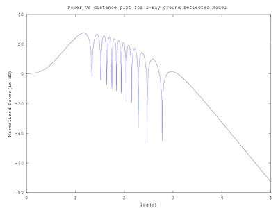
When d is small compared to transmitter height two waves add constructively to yield higher power and as d increases these waves add up constructively and destructively giving regions of up-fade and down-fade as d increases beyond the critical distance or first Fresnel zone power drops proportional to inverse fourth power of d. An approximation to critical distance may be obtained by setting Δφ to π as critical distance a local maximum.
As a case of log distance path loss model
The standard expression of Log distance path loss model is

The path loss of 2-ray ground reflected wave is
where
- ,


and

for the critical distance.

As a case of multi-slope model
The 2-ray ground reflected model may be thought as a case of multi-slope model with break point at critical distance with slope 20 dB/decade before critical distance and slope of 40 dB/decade after the critical distance.
See also
References
Goldsmith, Andrea (2004). Wireless communications (1. publ. ed.). Cambridge, U.K.: Cambridge University Press. ISBN 978-0521837163.
Institute, organized by The Korean Institute of Communications and Information Sciences ; Electronics and Telecommunications Research. ICTC 2012 2012 International Conference on ICT Convergence : "Global Open Innovation Summit for Smart ICT Convergence," October 15-17, 2012, Ramada Plaza Jeju Hotel, Jeju Island, Korea. Piscataway, NJ: IEEE. pp. 454–455. ISBN 978-1-4673-4827-0.
Rappaport, Theodore S. (2002). Wireless communications : principles and practice (2. ed.). Upper Saddle River, NJ: Prentice Hall PTR. ISBN 978-0130422323.